
Before You Begin
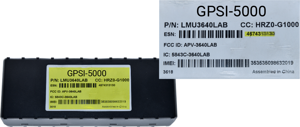
The installation kit contains the GPSI-5000 device, 24-pin harness, and a registration card with QR codes that take you to the installation guides and device verification-registration link.
Additional items and tools that you may need include a pen, dash panel removers, insulated crimpers, wire cutters, wire strippers, electrical tape, tamper seal, cable ties, ring terminal, ground screw, star washer, cordless drill, Phillips bit, razor blade/knife, and multimeter.
If you are intend to use this device in conjunction with ELD, please contact Support so that the appropriate script can be applied to your device(s).
Installation Steps
The following steps provide an overview of the installation process:
- Install Preparation.
- Harness Installation.
- Install Accessory
- Device Connections.
- Verify and Secure Install.
1. Install Preparation.
Locate the device, 24-pin harness, wire strippers, cable ties, wire cutter, registration card, pen and dash panel removers.- Record the 10-digit serial number (ESN) of the device onto your paperwork/registration card.
- Remove the dashboard panels for harness installation and device mounting.
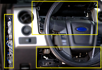
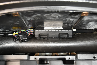
The device will be mounted behind the dash cluster.
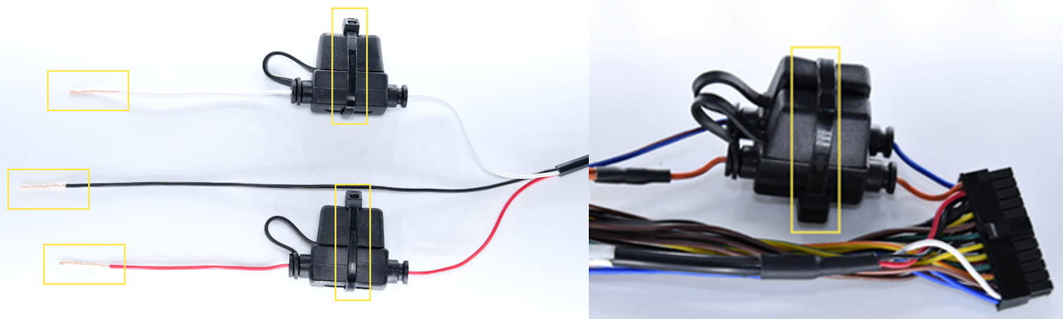
- Remove 1 1/2-in (4 cm) of insulation of the harnesses White, Red and Black wires, then twist the wire strands of each.
- Cable tie all inline fuse holders.
- Record the 10-digit serial number (ESN) of the device onto your paperwork/registration card.
2. Harness Installation.
Locate the multimeter, 24-pin harness, wire strippers, insulated crimpers, razor blade, electrical tape, star washer, ring terminal, ground screw, and cable ties.Important: If the 24-pin harness you are using for this installation has Harness Label: 5C735 REV B V2, then please follow the below chart for locating the appropriate Lead/Signal Wires to perform the following installation steps.

24-Pin Harness
- Locate a vehicle wire which provides between 12 VDC (+) and 24 VDC (+) while the vehicle is On and running and 0 VDC (+) when the key is in the Off and Accessory position. This will be the device’s Switch Source of power (Harness White Wire – Pin 15)
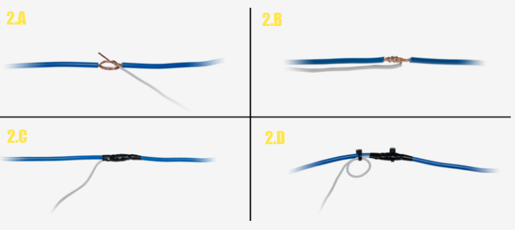
- Complete the following steps to poke and wrap the connection:
- Remove 1 in. (2.5 cm) of insulation from the vehicle wire identified and poke something nonconductive through the exposed wires to create a loop, then insert the exposed White wire strands into the loop.
- Squeeze the loop shut, and tightly wrap the bare wire around the exposed wire at least three times.
- Fold the wire back and generously wrap electrical tape around the connection, crossing over the insulation on both sides.
- Secure the connection with one cable tie directly over the wire-to-wire connection and another cable tie on a stress loop created about 1 in. (2.5 cm) away from the connection.
- Test for a vehicle wire that provides between 12 VDC (+) and 24 VDC (+) with the vehicle On, Off and Keys Removed. This will be the device’s Constant Source of power (Harness Red Wire – Pin 23).
- Complete the same poke and wrap steps mentioned above in Step 2.2: A-D, connecting the Red wire to the Constant Power Source.
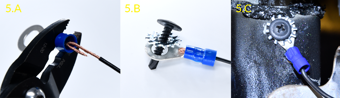
- Locate a suitable location on the chassis to mount the ground wire.
- Fold and crimp to the ring terminal.
- Slip the star washer over the self-tapping screw first, then through the ring terminal.
- After confirming there is nothing behind the mounting location, screw the ring terminal to the chassis.
- Route the harness to the area behind the dash cluster.
3. Install Accessories.
-
- If purchased, install the device accessories per their installation guide.
If purchased without accessories, tape off all unused 24-Pin harness wires and secure to harness with a cable tie.
-
4. Device Connections.
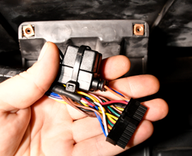
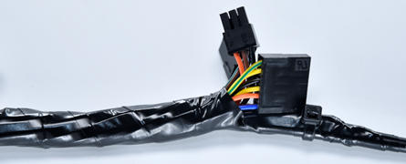
Locate the GPSI-5000 device.-
- Connect the 24-Pin harness and if applicable the 16-Pin diagnostic cable to the GPS device.
- Connect the 24-Pin harness and if applicable the 16-Pin diagnostic cable to the GPS device.
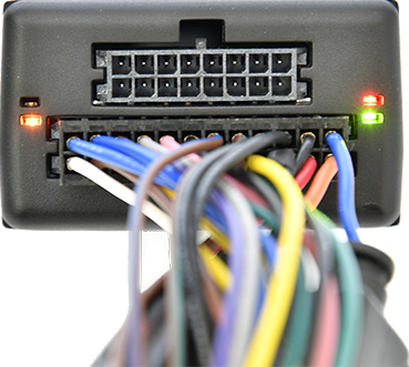
Lights will begin to blink slowly as the device powers on and will begin to blink faster as it searches for a signal. A solid amber light indicates it has received a cellular lock, and a solid green light indicates it has acquired a GPS lock.
- Mounting location must be high within the dashboard, white sticker facing up, behind the dash cluster and as close to the dashboard plastic as possible. Do not secure, but place the device in this area for testing.
-
5. Verify and Secure Installation.
Locate cell phone, registration card, cable ties, wire cutter and tamper seal.- Do not start the vehicle.
- To activate and register your device, with your vehicle card in hand, call 480-508-7478 or use the GPS Insight Verification App via smart phone (iOS | Android).
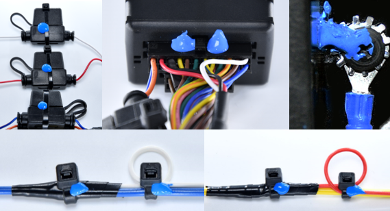
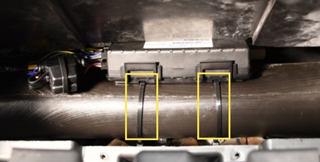
- After the installation has been verified, secure the cables and device with cable ties and tamper seal all connections.
- Tamper Seal:
- Mounting:
- Tamper Seal:
- Reassemble the vehicle’s dashboard and give the registration card to your GPS Administrator.
