
The installation kit contains a registration card, the 4000LD device, one external antenna, one 4-pin power harness, one 22-pin expansion harness, one vPOD cable, one OBD-II Pass-Thru Cable, one L-shaped OBD-II bracket, eight 8-in. (20 cm.) zip ties, and two 14-in. (35.5 cm.) zip ties.
Additional tools you need include a digital multimeter, cordless drill, razor knife, snips, wire strippers, electrical tape, zip ties, and tamper seal compound.
Installation Steps
The following steps provide an overview of the installation process:
- Install preparation.
- Antenna installation.
- OBD-II Pass-Thru Cable and vPOD installation.
- Ignition wire installation.
- Expansion harness installation.
- Cable connections.
- Verify and secure installation.
1. Install preparation.
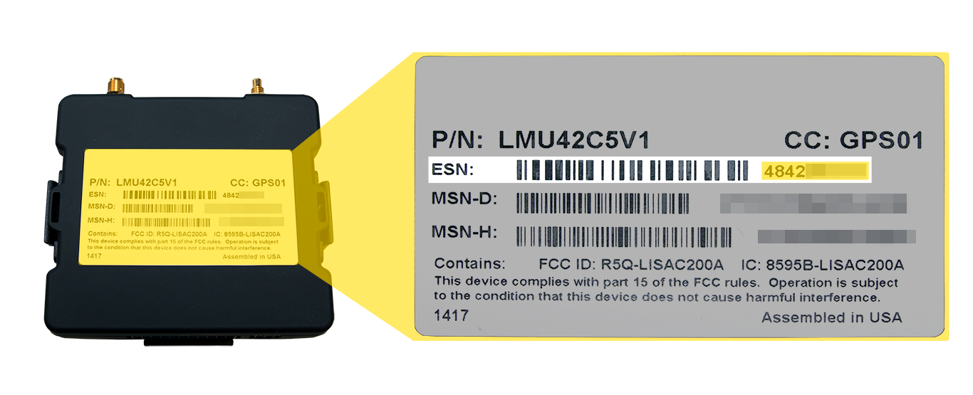
- Complete the registration card by locating the serial number of the GPS device and copying it on to the card.
4000LD Serial Number location:
- Remove the a-pillar plastic and dashboard panels to gain access to the area behind the dashboard cluster.
- Turn the vehicle’s master cut-off switch to the ON position (if the vehicle is equipped with one).
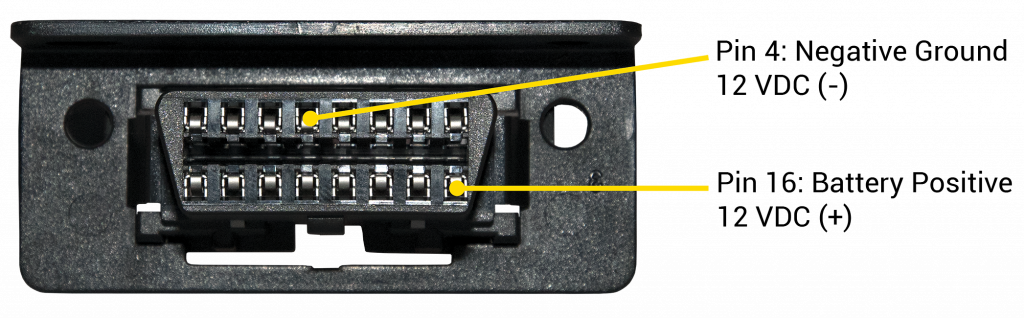
- Locate the vehicle’s OBD-II diagnostic port under the dashboard.
- Using a digital multimeter, test the constant power at the port by placing the positive probe on pin 16 and the negative probe on pin 4. In order to proceed, the port must provide between 12 and 24 VDC (+) when the vehicle is on or off (keys removed).
If the port does not provide the recommended voltage or no voltage at all, check the vehicle battery or replace the diagnostic port fuse, reconfirm power, then proceed to the next step.
- Complete the registration card by locating the serial number of the GPS device and copying it on to the card.
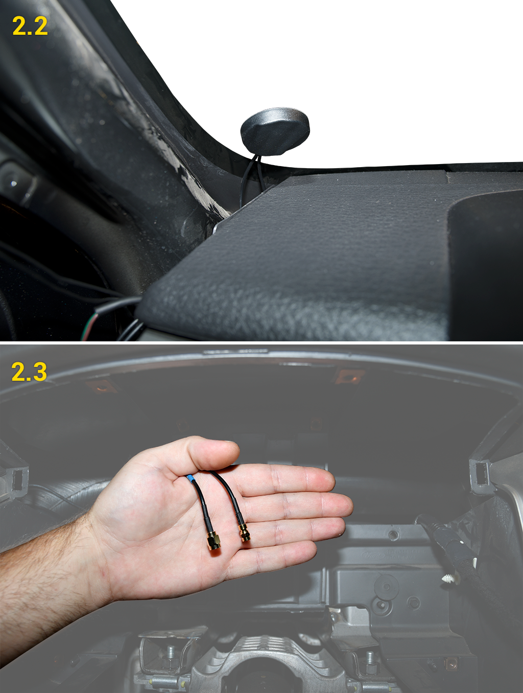
2. Antenna installation.
The mounting location for the antenna is inside the vehicle on a clear section of the windshield in the lower-left corner, as close to the dashboard as possible.- Prepare the section of the windshield for mounting by wiping it down with a dry cloth.
- Remove the backing paper under the antenna to expose the antenna’s adhesive, and press the antenna firmly against the windshield to eliminate as many air pockets as possible.
- Route the antenna cables behind the dashboard cluster toward the mounting location of the GPS device. Stay clear of any moving parts, and ensure the cables will not be pinched or cut when the dashboard is reassembled.
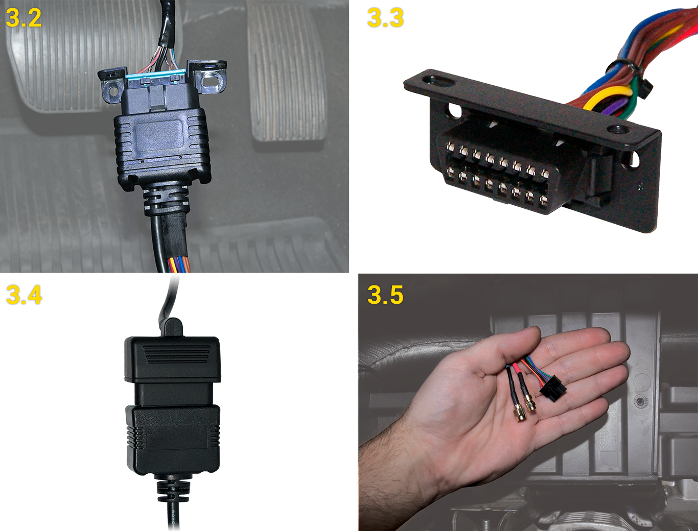
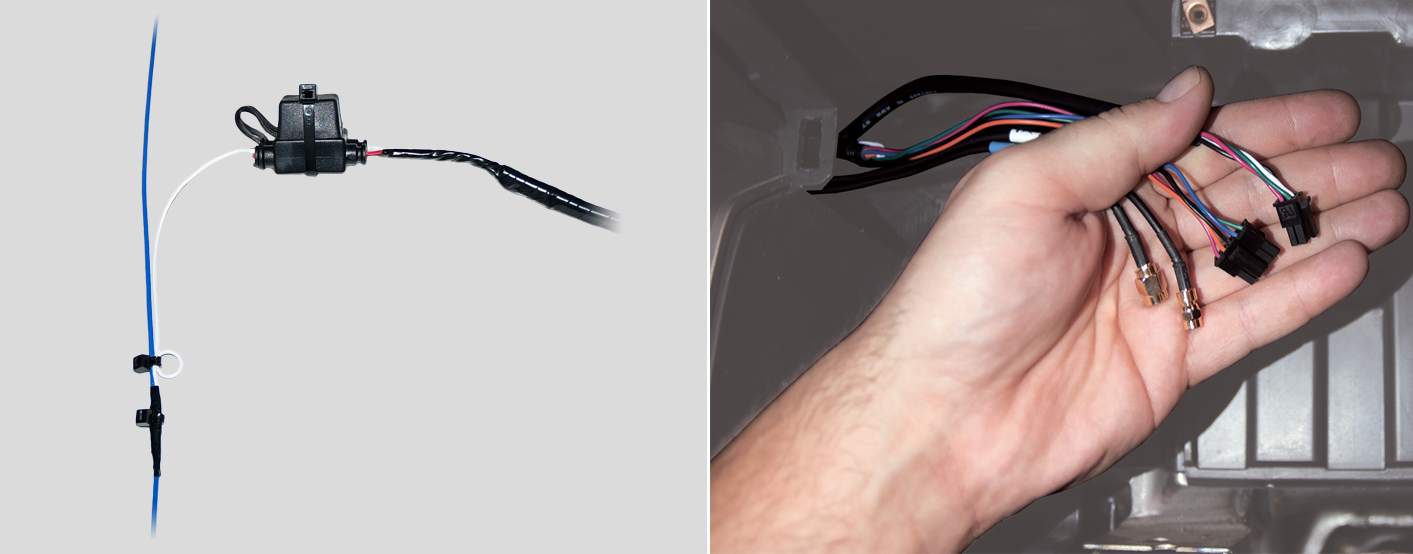
3. OBD-II Pass-Thru Cable and vPOD installation.
- Locate the vPOD cable, tape the loose white wire to the harness, and then secure it with a zip tie.
- Free up the existing diagnostic port from its current location in the vehicle, and plug the OBD-II Pass-Thru Cable into the vehicle’s diagnostic port.
- Place the L-shaped OBD-II bracket over the OBD-II Pass-Thru Cable replacement port and snap it into place. Mount the replacement diagnostic port using the original screws/nuts.
- Plug the vPOD into the OBD-II Pass-Thru Cable.
- Route the vPOD’s 5-pin connector behind the dashboard cluster toward the mounting location of the GPS device. Stay clear of any moving parts, and ensure the cable will not be pinched or cut when the dashboard is reassembled.


4. Harness Installation.
Locate the multimeter, 4-pin harness, wire strippers, insulated crimpers, razor blade, electrical tape, star washer, ring terminal, ground screw, and cable ties.4-Pin Harness
- Locate a vehicle wire which provides between 12 VDC (+) and 24 VDC (+) while the vehicle is On and running and 0 VDC (+) when the key is in the Off and Accessory position. This will be the device’s Switch Source of power (Harness White Wire – Pin 4)
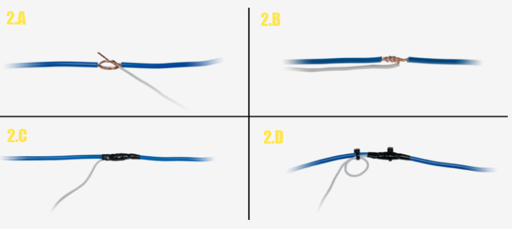
- Complete the following steps to poke and wrap the connection:
- Remove 1 in. (2.5 cm) of insulation from the vehicle wire identified and poke something nonconductive through the exposed wires to create a loop and insert the exposed White wire strands into the loop.
- Squeeze the loop shut, and tightly wrap the bare wire around the exposed wire at least three times.
- Fold the wire back and generously wrap electrical tape around the connection, crossing over the insulation on both sides.
- Secure the connection with one cable tie directly over the wire-to-wire connection and another cable tie on a stress loop created about 1 in. (2.5 cm) away from the connection.
- Test for a vehicle wire that provides between 12 VDC (+) and 24 VDC (+) with the vehicle On, Off and Keys Removed. This will be the device’s Constant Source of power (Harness Red Wire – Pin 1).
- Complete the same poke and wrap steps mentioned above in Step 2.2: A-D, connecting the Red wire to the Constant Power Source.
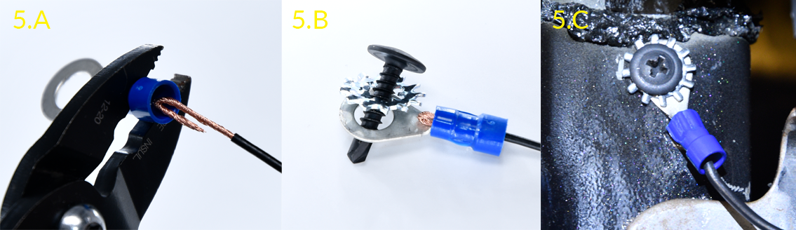
- Locate a suitable location on the chassis to mount the ground wire.
- Fold and crimp to the ring terminal.
- Slip the star washer over the self-tapping screw first, then through the ring terminal.
- After confirming there is nothing behind the mounting location, screw the ring terminal to the chassis.
- Route the 4-pin power harness connector behind the dashboard cluster toward the mounting location of the GPS device. Stay clear of any moving parts, and ensure the cable will not be pinched or cut when the dashboard is reassembled.
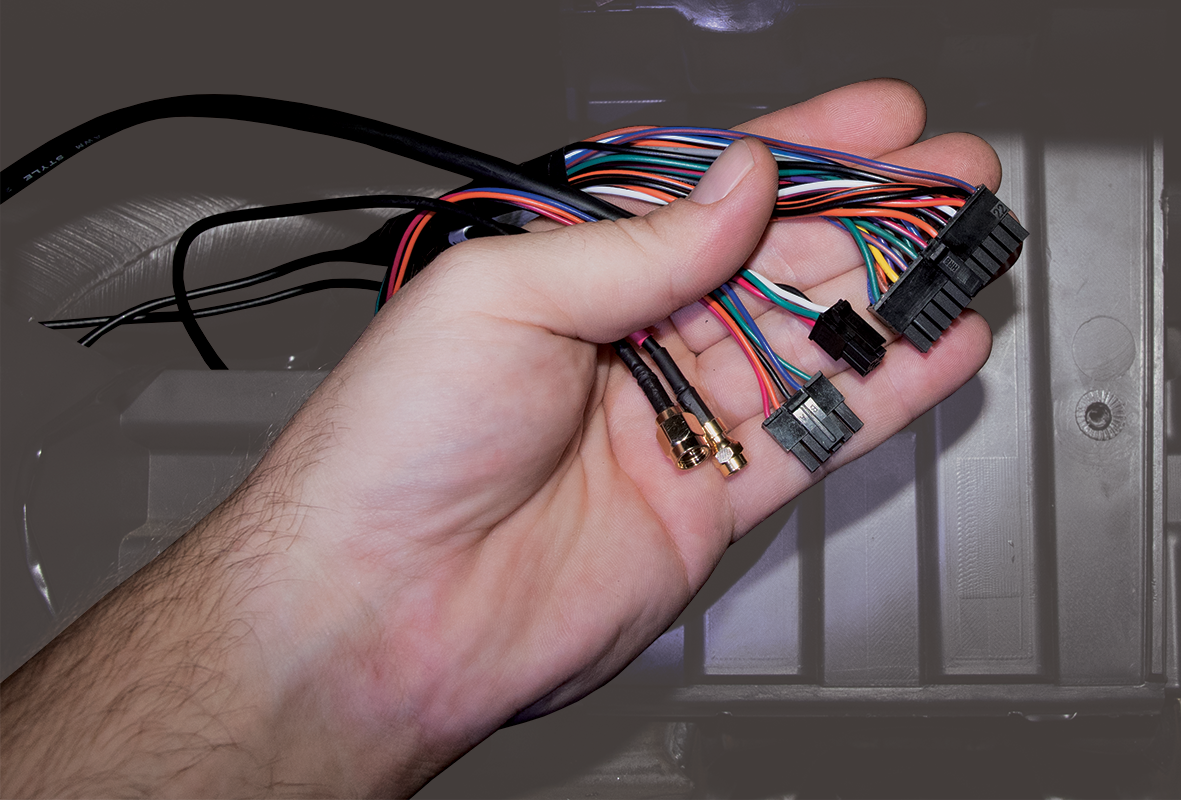
5. Expansion harness installation.
If your installation has any accessories, please refer to the corresponding guide now. Once connected, route the expansion harness behind the dashboard cluster toward the mounting location of the GPS device.- If no accessories are being installed, locate the 22-pin expansion harness, tape the ends of all the wires, and connect it to the GPS device port labeled I/O.
6. Cable connections.
- Connect both antenna connections to the GPS device. Make sure the connections are finger-tight; do not over-tighten and damage the cables.
- Connect the 4-pin harness to the back of the GPS device port labeled Power, and the 22-pin expansion harness to the port labeled I/O.
- Connect the 5-pin vPOD connector to the GPS device port labeled AUX 1.
As the GPS device powers up, observe the GPS and Cellular LEDs. Both LEDs will blink slowly and will begin to blink faster as it searches for signal. A solid amber LED indicates a cellular lock, and a solid green LED indicates a GPS lock.
7. Verify and secure the installation.
- Do not start the vehicle.
- To activate and register your device, with your vehicle card in hand, call 480-508-7478 or use the GPS Insight Verification App via smart phone (iOS | Android).
- After the installation has been verified, secure the installation with zip ties and tamper seal:
- Mount the GPS device behind the dashboard cluster to a vent pipe or chassis support, coil any unused wire, and then secure them within the dashboard.
- Reassemble the vehicle’s dashboard and give the registration card to your GPS administrator.