
Before You Begin
The installation kit contains the GPSI-5000 GPS device, 24-pin harness, one Android MDT (tablet), one MDT dock, one ELD data cable, one Dock Mount (incl. backing plate and applicable hardware), Diagnostic Cable (if applicable), ring terminal, ground screw, star washer, four 2.5 mm. hex screws, one rubber grommet, 14-in, and 8-in cable ties, installation guide and registration card.
Additional tools that you may need include a pen, dash panel removers, insulated crimpers, wire cutters, wire strippers, electrical tape, tamper seal, cordless drill, P2 Phillips bit, PHO Phillips screwdriver, 5/8-in. (16 mm.) drill bit, 3/16-in. (5 mm.) a drill bit, razor blade/knife, adjustable wrench, and multimeter.
If installing into older vehicles where ignition or constant power cannot be obtained via the diagnostic port, please refer to the GPSI-5000: Conventional Hardwire Guide to wire the 24-Pin Harness before proceeding.
Installation Steps
The following steps provide an overview of the installation process:
- Install Preparation.
- Cable Installation.
- Tablet Mount Installation.
- Install Accessory.
- Device Connections.
- Verify and Secure Install.
1. Install Preparation.
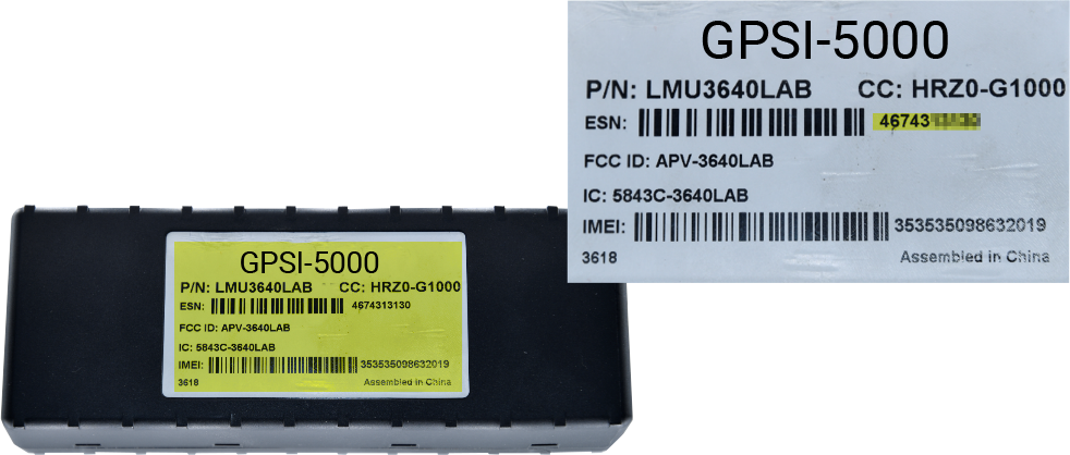
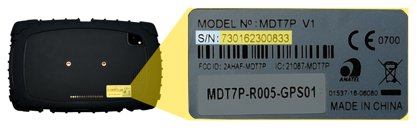
Locate the device, MDT tablet, 24-pin harness, wire strippers, cable ties, wire cutter, registration card, pen, and dash panel removers.- Record the 10-digit serial number (ESN) of the device and the 12-digit tablet serial number (S/N) onto your paperwork/registration card.
GPSI-5000 Serial Number Location:
Android MDT (tablet) Serial Number Location:
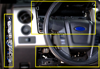
- Remove the dashboard panels for harness installation and device mounting.
- Record the 10-digit serial number (ESN) of the device and the 12-digit tablet serial number (S/N) onto your paperwork/registration card.
2. Cable Installation.
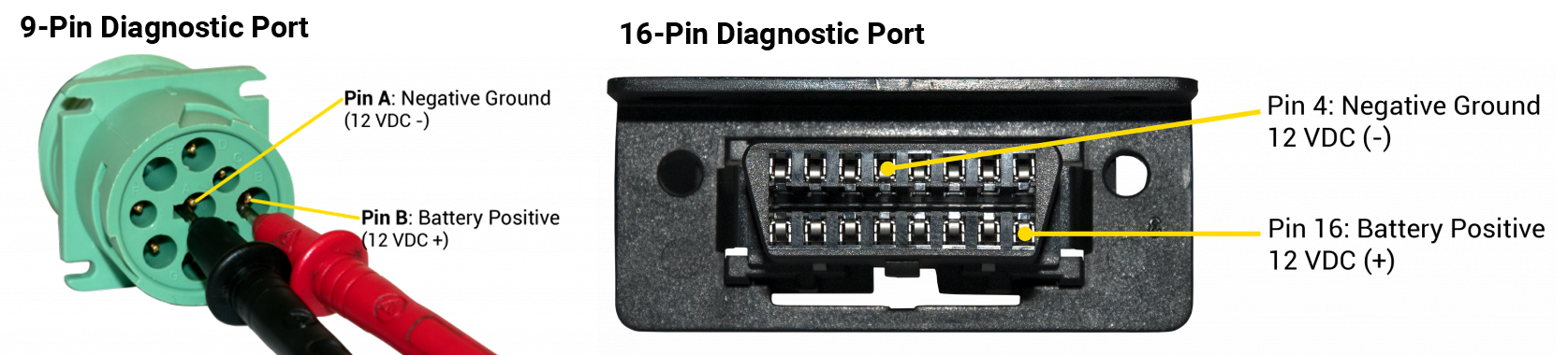
- Ensure the key is removed from the ignition, then locate the vehicle’s diagnostic port under the dashboard. Using a digital multimeter, test for constant power at the port:
- 9-Pin Diagnostic Connector: Place the positive probe on Pin B and the negative probe on Pin A.
- 16-Pin Diagnostic Connector: Place the positive probe on Pin 16 and the negative probe on Pin 4.
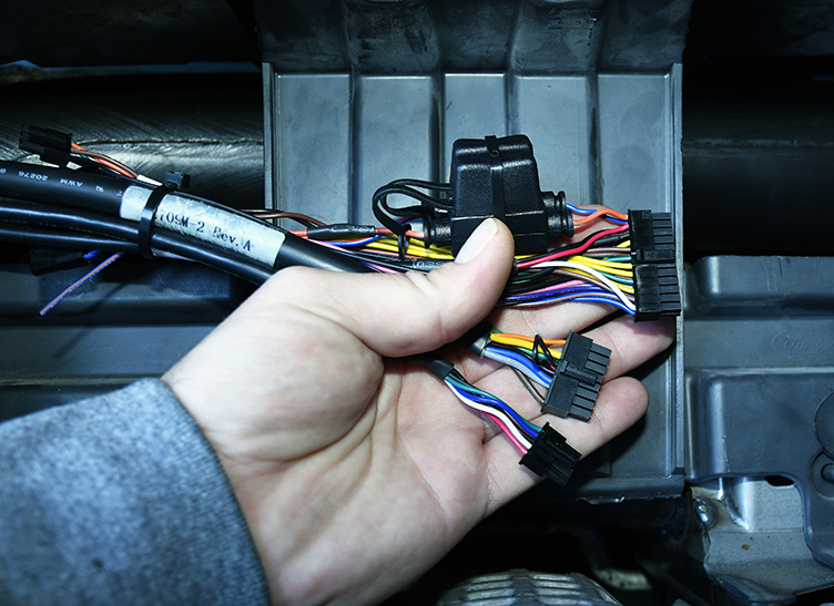
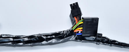
- Free up the existing diagnostic port from its current location in the vehicle and plug the pass-thru cable connector into the vehicle’s diagnostic port.
- Mount the replacement diagnostic port.
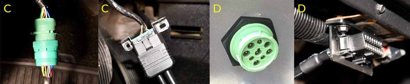
- Route the pass-thru cable through the dashboard cluster toward the mounting location of the GPS device. Stay clear of any moving parts, and ensure the cable will not be pinched or cut when the dashboard is reassembled.
If the port does not provide between 12 VDC and 24 VDC (+) when the vehicle is on or off (keys removed), has a master cut-off, or the vehicle is pre-diagnostic, please follow the instructions listed in the Pass-Thru Cable Power Reroute Guide, or contact Technical Support for further assistance.
- Ensure the key is removed from the ignition, then locate the vehicle’s diagnostic port under the dashboard. Using a digital multimeter, test for constant power at the port:
3. Tablet Mount Installation.
Locate the MDT dock, Dock Mount, backing plate kit, 5/8 in. (16 mm) and 3/16 in. (5 mm) drill bit, cordless drill, fine tip marker, grommet, P2 Philips bit, PH0 Philips screwdriver, adjustable wrench, screws, security cover, security cover screws and two cable ties.- When determining the mounting location, keep in mind the size of the Android MDT (tablet) and length of the ELD data cable; the Android MDT (tablet) must be within reaching distance of the driver while seated and NO part of the tablet should be above the top of the dashboard, or obstruct usage of any gauges or switches.
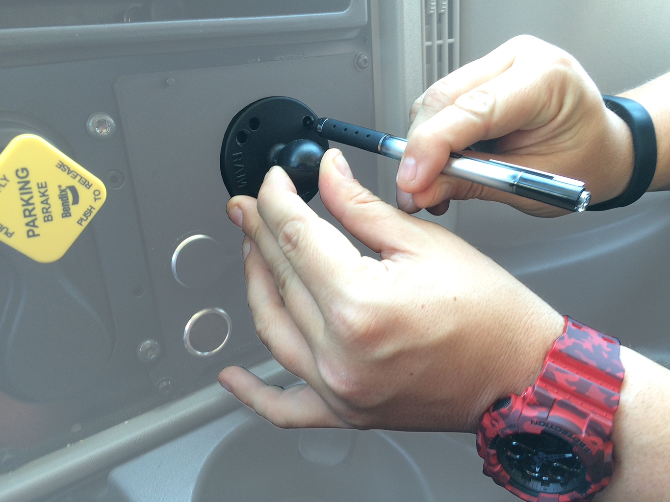
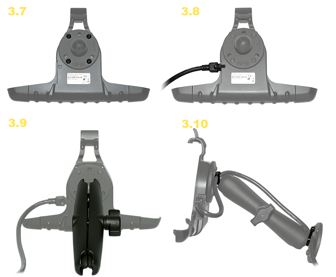
- Separate the mount base by loosening the tightening screw in the middle of the arm.
- Using the mount base and backing plate, identify the holes by lining up the two before marking the holes needed to secure the mount to the dashboard.
Before you continue, verify there are no wires, air lines, or anything else behind the mounting location that might be damaged by the drill bit.
- Drill out the four holes marked in the previous step with the 3/16-in. (5 mm.) drill bit, and then line up the base of the Dock Mount with the backing plate and secure it to the dashboard using the four nuts and bolts included in your kit.
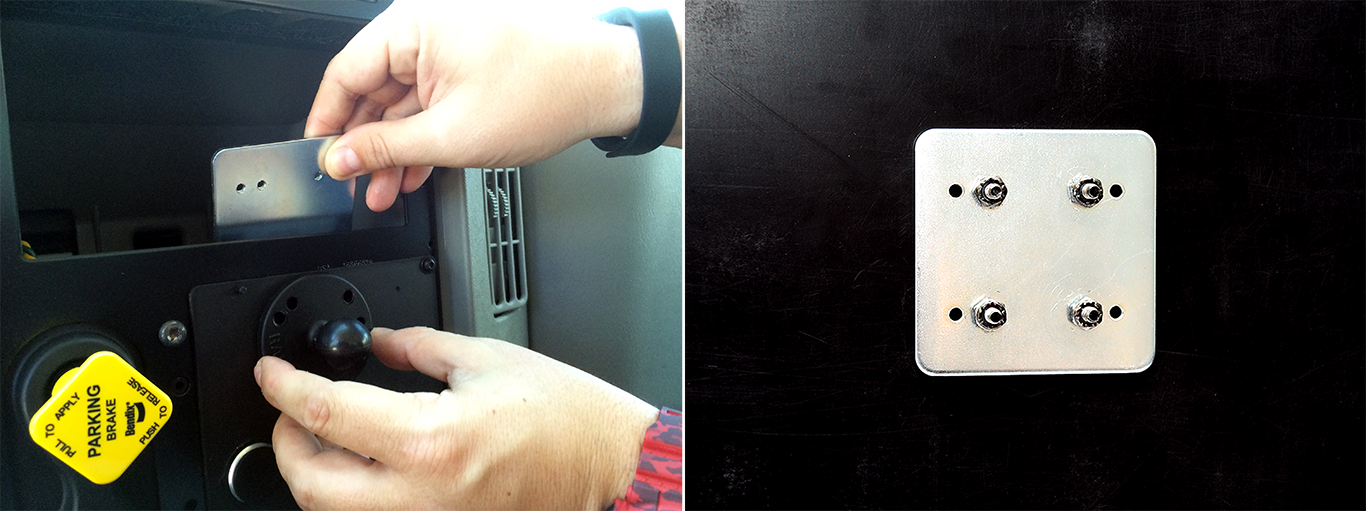
The backing plate is required for every install. If you are unable to use the backing plate without significant modifications, consult with your project coordinator. Do not secure the mount to the dashboard with self-tapping screws.
- Identify a location near the base of the mount that is hidden once the tablet is docked, and drill a hole approximately 5/8 in. (16 mm.) in diameter.
- Feed the 6-pin connector through the hole, then cut and slide the grommet into place.
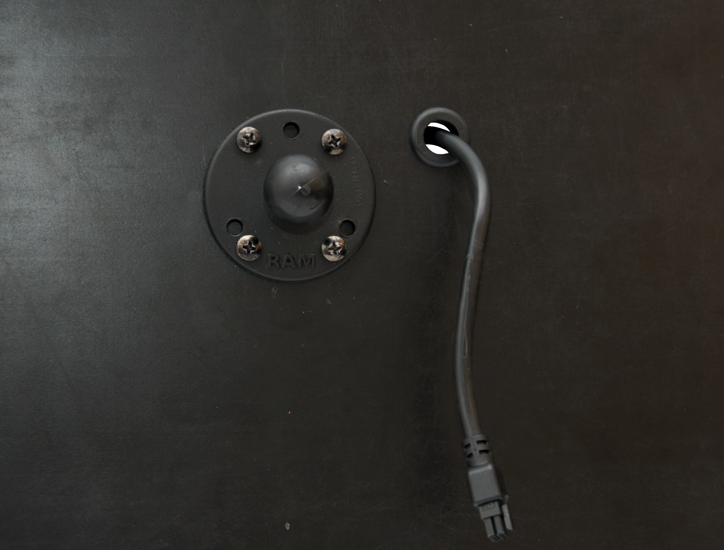
- Using the four hex screws provided and a 2.5 mm. hex key, secure the other mount base to the back of the MDT dock.
- Connect the ELD data cable’s 6-pin connector to the back of the MDT dock.
- Locate the mount arm and loosen the knob to partially release the spring. Place one ball joint in one of the arm’s sockets, and the other ball joint in the other arm socket. Adjust the positioning of the MDT dock to the desired position as you tighten the mount arm.
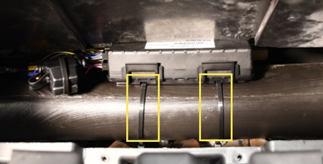
- Secure the cable to the mount arm using zip ties.
- Route ELD data cable’s 5-pin connector behind the dashboard cluster toward the mounting location of the GPS device. Stay clear of any moving parts, and ensure the cable will not be pinched or cut when the dashboard is reassembled.
4. Install Accessories.
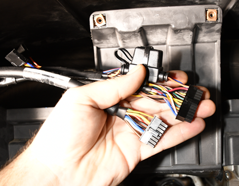
- If purchased, install the device Accessories per their installation guide and tape off all unused wires.
If purchased without accessories, tape off all unused 24-Pin harness wires and secure to harness with a cable tie.
5. Device Connections.
Locate the GPSI-5000 device.
- Connect the ELD cable to Serial Port 1 before connecting the 24-Pin harness to the device, followed by the 16-Pin diagnostic cable.
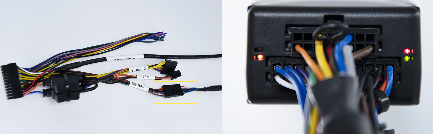
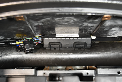
- Mounting location must be high within the dashboard, white sticker facing up, behind the dash cluster, and as close to the dashboard plastic as possible. Do not secure, but place the device in this area for testing.
Lights will begin to blink slowly as the device powers on and will begin to blink faster as it searches for a signal. A solid amber light indicates it has received a cellular lock, and a solid green light indicates it has acquired a GPS lock.
6. Verify and Secure Installation.
Locate cell phone, registration card, cable ties, wire cutter, and tamper seal.
- To activate and register your device, with your vehicle card in hand, please call 480-508-7478.
- Be prepared–Technical Support instructions will consist of the following:
- Start vehicle; engine running.
- Confirm the tablet powers up on its own and indicates it is charging.
- Verify accessories (if applicable).
- Turn the vehicle off.
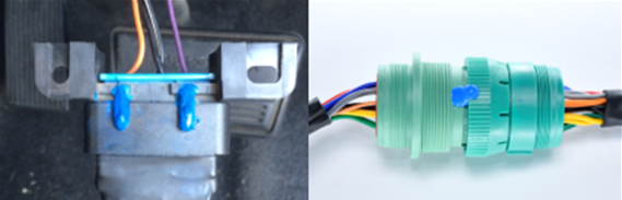
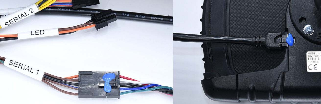
- After the installation has been verified, secure the cables and device with cable ties and tamper seal all connections.
- Tamper Seal:
- Mounting:
- Reassemble the vehicle’s dashboard and give the registration card to your GPS Administrator.