
Before You Begin
The installation kit contains a registration card, the 4000HD device, one external antenna, one 4-pin power harness, one 22-pin expansion harness, one 9 Pin 500k Pass-Thru cable, one Android MDT (tablet), one MDT dock, one ELD data cable, one RAM mount (incl. backing plate and applicable hardware), four 2 1/2 mm. hex screws, one rubber grommet, eight 8-in. (20 cm.) zip ties, and two 14-in. (35 1/2 cm.) zip ties.
Additional tools you need include a digital multimeter, cordless drill, 5/8-in. (16 mm.) drill bit, 3/16-in. (5 mm.) drill bit, 2 1/2 mm. hex key, razor knife, snips, wire strippers, electrical tape, zip ties, and tamper seal compound.
Installation Steps
The following steps provide an overview of the installation process:
- Install preparation.
- Antenna installation.
- Pass-Thru Cable installation.
- Reverify constant power.
- Ignition wire installation.
- Expansion harness installation.
- RAM mount installation.
- MDT dock installation.
- Cable connections.
- Verify and secure the installation.
1. Install preparation.
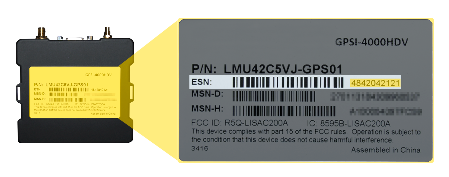
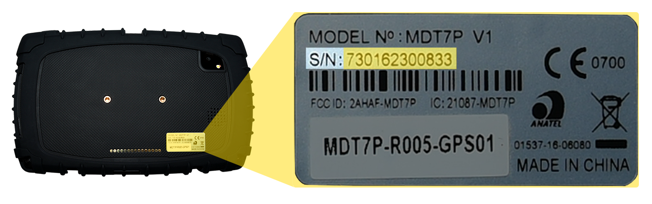
- Complete the registration card by locating the serial number of the GPS device and Android MDT (tablet) and copying it onto the card.
4000HD Serial Number location
Android MDT (tablet) Serial Number location
- Remove the a-pillar plastic and dashboard panels to gain access to the area behind the dashboard cluster.
- Turn the vehicle’s master cut-off switch to the ON position (if the vehicle is equipped with one).
- Locate the vehicle’s 9-pin diagnostic port under the dashboard.
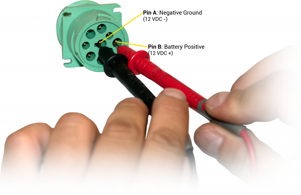
- Using a digital multimeter, test the constant power at the port by placing the positive probe on pin B and the negative probe on pin A. In order to proceed, the port must provide between 12 and 24 VDC (+) when the vehicle is on or off (keys removed).
- Complete the registration card by locating the serial number of the GPS device and Android MDT (tablet) and copying it onto the card.
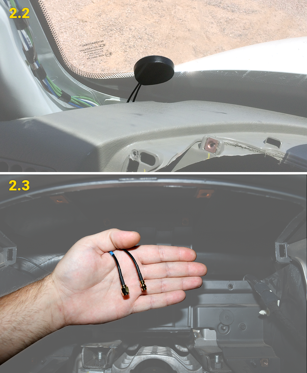
2. Antenna installation.
The mounting location for the antenna is inside the vehicle on a clear section of the windshield in the lower-left corner, as close to the dashboard as possible.- Prepare the section of the windshield for mounting by wiping it down with a dry cloth.
- Remove the backing paper under the antenna to expose the antenna’s adhesive, and press the antenna firmly against the windshield to eliminate as many air pockets as possible.
- Route the antenna cables behind the dashboard cluster toward the mounting location of the GPS device. Stay clear of any moving parts, and ensure the cables will not be pinched or cut when the dash is reassembled.
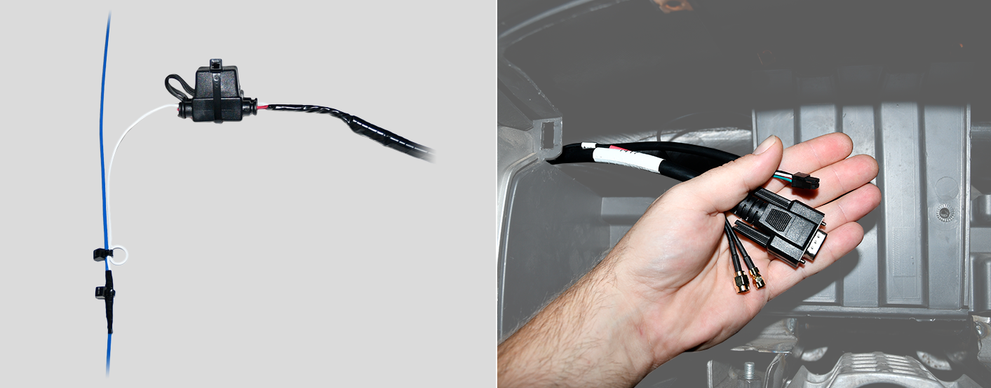
3. Pass-Thru Cable installation.
- Free up the existing diagnostic port from its current location in the vehicle.
- Plug the pass-thru cable connector into the vehicle’s diagnostic port, and turn the threaded coupling to lock the two pieces together.
- Mount the replacement diagnostic port using the original screws or locking nut.
- Route the pass-thru cable through the dashboard cluster toward the mounting location of the GPS device. Stay clear of any moving parts, and ensure the cable will not be pinched or cut when the dashboard is reassembled.

4. Reverify constant power.
Due to the GPS device requiring constant power at all times and some vehicles being equipped with a timed master cut-off switch, another voltage check is required before you continue.
Using a digital multimeter, test the constant power at the port by placing the positive probe on pin B and the negative probe on pin A. In order to proceed, the port must provide between 12 and 24 VDC (+) when the vehicle is on or off (keys removed).
If the port does not provide 12 to 24 VDC (+), please follow the instructions listed in the HD Pass-Thru Cable Power Reroute Guide, or contact Technical Support for further assistance.
5. Ignition wire installation.
Using a digital multimeter, locate an ignition source that provides at least 12 VDC (+) while the key is in the On position, and 0 VDC (+) when the key is in the Off or Accessory position. Once identified, remove the keys from the ignition and proceed with the steps listed below.-
- Find a loose section of the ignition source wire, remove 1 in. (2 1/2 in.) of insulation with a razor knife/wire strippers, and gently poke something non-conductive between the exposed wires to create an even loop.
- Locate the 4-pin power harness included in your kit and strip off about 1 1/2 in. (4 cm.) of insulation from the end of the fused white wire.
- Using electrical tape, tape off the red, black, and green wires on the power harness.

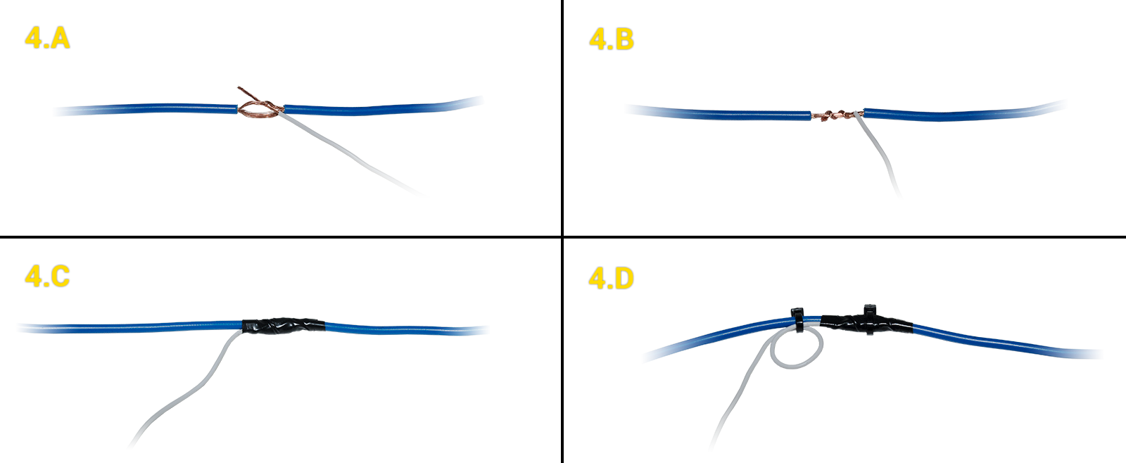
- Secure the 4-pin power harness white wire to the ignition source using the poke-and-wrap technique:
- Twist the end of the white wire and poke it through the loop that you created.
- Squeeze the loop shut, and tightly wrap the bare wire around the exposed wire at least 3 times.
- Fold the wire back, and generously wrap electrical tape around the connection, crossing over the insulation on both sides.
- Secure the connection with one zip tie directly over the wire-to-wire connection and another zip tie on a stress loop created about 1 in. (2 1/2 cm.) away from the connection.
- Route the 4-pin power harness connector behind the dashboard cluster toward the mounting location of the GPS device. Stay clear of any moving parts, and ensure the cable will not be pinched or cut when the dashboard is reassembled.
-
6. Expansion harness installation.
If your installation has any accessories, please refer to that guide now. Once connected, route the expansion harness behind the dashboard cluster toward the mounting location of the GPS device.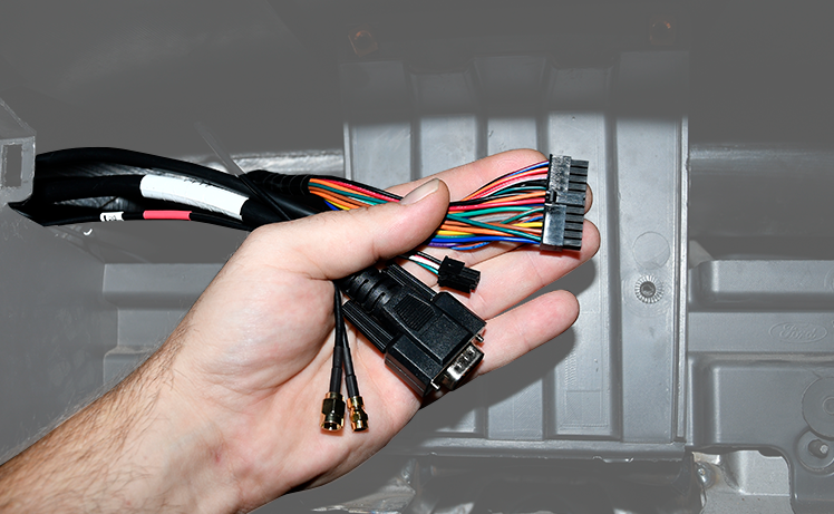
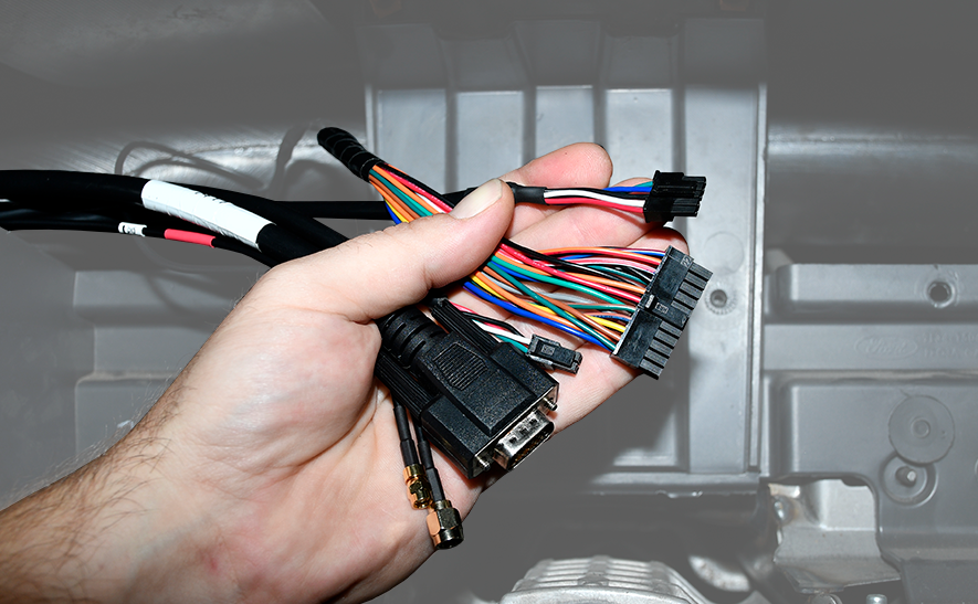
If no accessories are being installed, locate the 22-pin expansion harness, tape the ends of all the wires, and then connect it to the GPS device port labeled I/O.
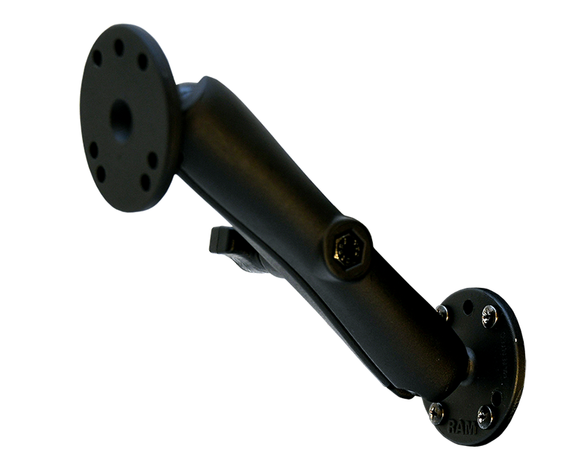
7. RAM mount installation.
Follow the instructions to install the fixed RAM mount.
Mounting Location
- When determining the mounting location, keep in mind the size of the Android MDT (tablet) and length of the ELD data cable; the Android MDT (tablet) must be within reaching distance of the driver while seated and NO part of the tablet should be above the top of the dashboard, or obstruct usage of any gauges or switches.
Android MDT (tablet): 8 5/8 x 5 1/2 x 15/16 in. (220 x 138 x 24 mm.); ELD data cable: 96 in. (2 2/5 m.).
- Using the RAM mount base, mark the holes needed to secure the mount to the dashboard.
Before you continue, verify there are no wires, air lines, or anything else behind the mounting location that might be damaged by the drill bit.
Installing the Mount
- Drill out the four holes marked in the previous step, and then line up the base of the RAM mount with the backing plate and secure it to the dashboard using the four nuts and bolts included in your kit.
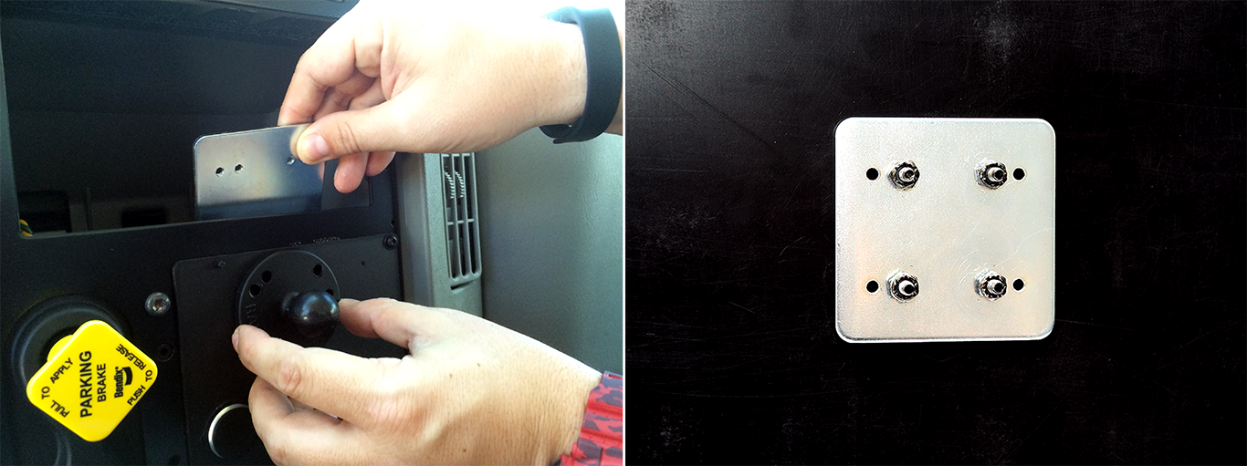
The backing plate is required for every install. If you are unable to use the mount without significant modifications, drill the holes and use the supplied nuts and bolts. Do not secure the RAM mount to the dashboard with self-tapping screws.
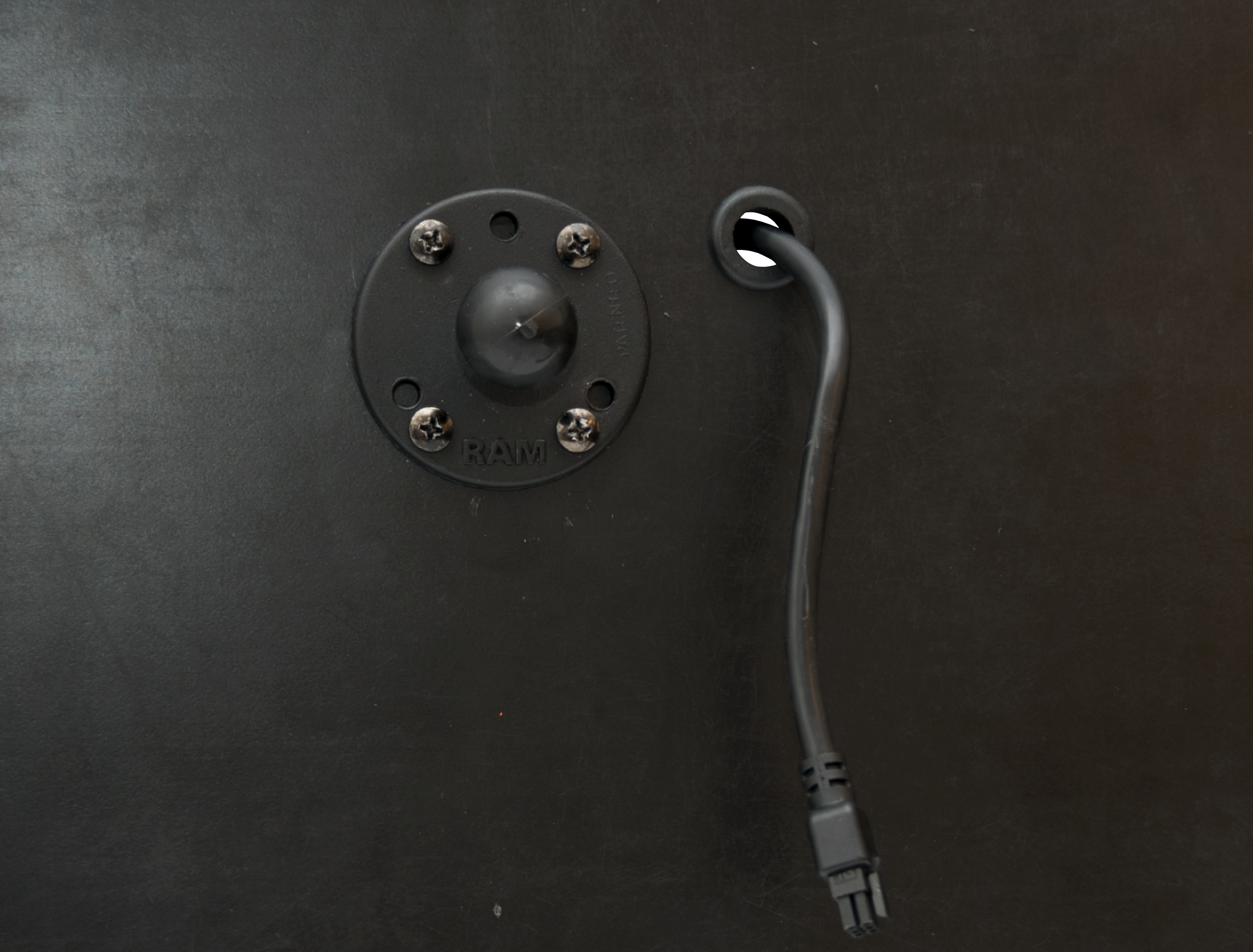
- Using a unibit, or 5/8-in. drill bit, identify a location near the base of the RAM mount that is hidden once the tablet is docked, and drill a hole approximately 5/8 in. (16 mm.) in diameter.
- Locate the ELD data cable and rubber grommet, and feed the 6-pin end of the cable through the hole. Place the grommet over the end of the cable and secure it inside the hole as shown below.
8. MDT dock installation.
-
-
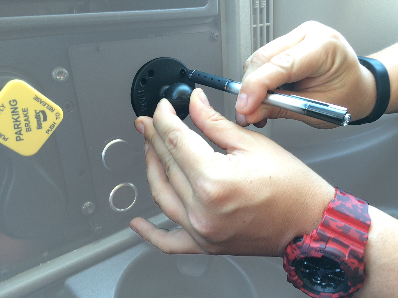
- Using the four hex screws provided and a 2 1/2 mm. hex key, secure the other RAM mount base to the back of the MDT dock.
- Connect the ELD data cable’s 6-pin connector to the back of the MDT dock.
- Locate the RAM mount arm and loosen the knob to partially release the spring. Place one ball joint in one of the arm’s sockets, and the other ball joint in the other arm socket. Adjust the positioning of the MDT dock to the desired position as you tighten the mount arm.
- Secure the cable to the mount arm using zip ties.

-
-
-
- Route the ELD data cable’s 5-pin connector behind the dashboard cluster toward the mounting location of the GPS device. Stay clear of any moving parts, and ensure the cable will not be pinched or cut when the dashboard is reassembled.
-
-
9. Cable connections.
-
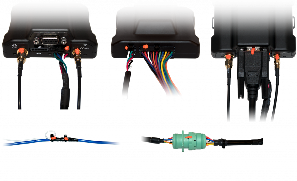
- Connect both antenna connections to the GPS device. Make sure the connections are finger-tight; do not over-tighten and damage the cables.
- Connect the ELD data cable’s 5-pin connector to the GPS device port labeled AUX 2.
- Connect the 4-pin harness to the back of the GPS device port labeled Power, and the 22-pin expansion harness to the port labeled I/O.
- Connect the serial connector from the pass-thru cable to the GPS device port labeled JPOD.
As the GPS device powers up, observe the GPS and Cellular LEDs. Both LEDs will blink slowly and will begin to blink faster as it searches for signal. A solid amber LED indicates a cellular lock, and a solid green LED indicates a GPS lock.
- Once both LEDs are solid, connect the Android MDT (tablet) to the MDT dock by placing the bottom of the tablet in first, and then lightly pushing the top of the tablet back until it clicks into place.

-
10. Verify and secure the installation.
- Do not start the vehicle.
- To activate and register your device, with your completed registration card in hand, call 480-508-7478.
- Be prepared–Technical Support instructions will consist of the following:
- Start vehicle; engine running.
- Confirm the Android MDT (tablet) powers up on its own and indicates it is charging.
- From the Android MDT (tablet), open the Vehicle Data Services app
 and confirm the following:
Field Value Odometer (km) Technical Support will convert this value and confirm it matches your dashboard odometer. Ignition On True BB Connected True ECU Connected True Comms Connected Connected - From the Android MDT (tablet), open the eFleetSuite app
 and enter the following information:
Field Value Device ID Delete current value and enter the tablet serial number from your registration card. Vehicle ID Enter the vehicle ID provided by the project coordinator. Organization ID Enter exactly what was provided by the project coordinator. Provisioning Key Enter exactly what was provided by the project coordinator. Host Name Enter exactly what was provided by the project coordinator. Port Enter exactly what was provided by the project coordinator. - Tap Done.
- Verify accessories (if applicable).
- Turn the vehicle off.
- Once approved by Technical Support, secure the installation:
- Apply tamper seal to all connections:
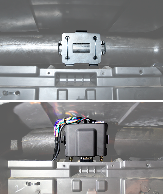
- Mount the GPS device behind the dashboard cluster to a vent pipe or chassis support, coil any unused wires, and then secure them within the dashboard.
- Apply tamper seal to all connections:
- Reassemble the vehicle’s dashboard and give the registration card to your GPS administrator.