Before You Begin
The installation kit contains a registration card, the 3900 device, and a 20-pin harness. Additional tools and supplies that you will need include a digital multimeter, a crimping tool, a razor knife, wire strippers, a ring terminal, plastic cable ties, electrical tape, tamper seal compound, self tapping screw, and a star washer.
Complete the registration card by locating the serial number of the device (labeled “ESN” or “SN”) and copying it onto the card. When the card is complete, you’re ready to start the installation.
Installation Overview
The following steps provide an overview of the installation process:
- Locate wires with proper voltage for constant and switch power.
- Connect the constant, switch, and ground wires. Also, locate the vehicle chassis for ground connection (not dash metal).
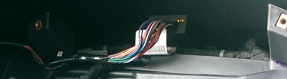
- Tape the harness wires, and connect the harness to the device.
- Mount the device high within the dash (white sticker facing up).
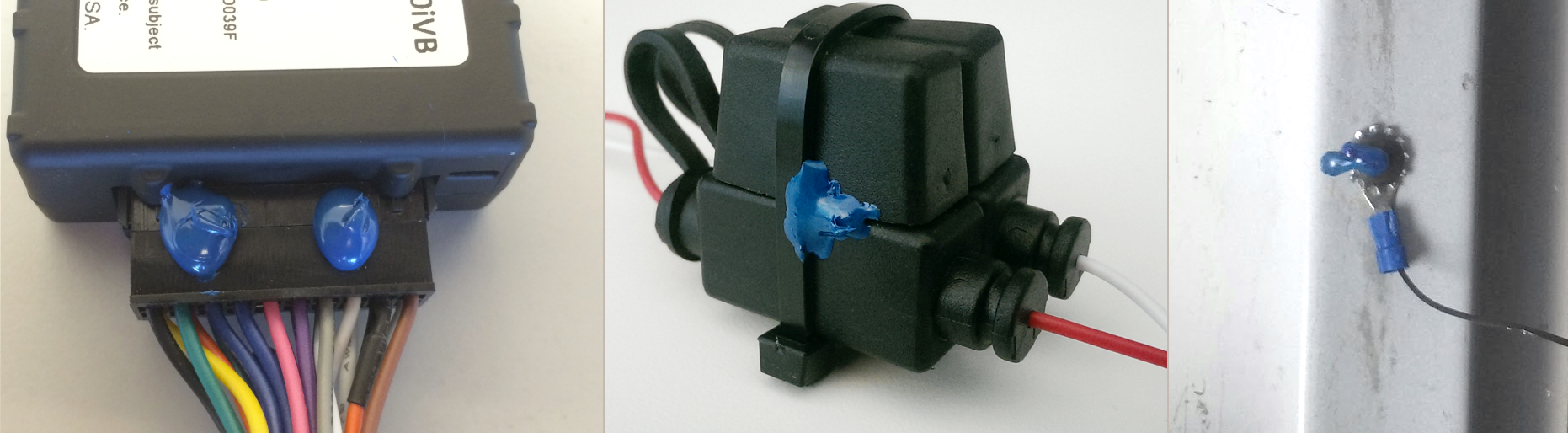
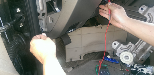
- Verify installation, and tamper-proof remaining connections.
– INSTALL OPTIONAL ACCESSORIES –
Installation Steps
1. Locate wires with proper voltage for constant and switch power.
- Remove the lower, side, and upper dashboard panels as well as the vehicle’s instrument cluster.
- With the ignition off and the key removed, use a digital multimeter to locate a wire that is consistently receiving between 12 to 24 volts; this wire will be the constant power source.
- Identify a wire that supplies between 12 to 24 volts when the key is in the Ignition On position but 0 volts when the key is in the Off or Accessory position; this wire will be the switch power source.
Red = Constant +12V. White = Switched +12V with ignition On, 0V with ignition Off or in Accessory. Black = Ground
2. Connect the constant, switch, and ground wires.
- Locate the wire you’ve isolated as the constant power supply, and remove an inch of insulation of the wire with a razor knife and wire strippers.
- Poke through the exposed wire to create a loop.
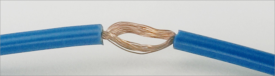
- From the device harness, locate the RED constant power wire, and strip off about 1 1/2 inches of the insulation from the end of the wire.
- Twist the ends, and poke it through the loop that you just created. Squeeze the loop shut, and wrap the bare wire around the loop at least 3 times. Fold the RED wire back over the loops, and then wrap the connection in electrical tape. Use two plastic cable ties, one directly over the wire-to-wire connection, and one to secure the stress loop about 2.5 cm/1 inch away.
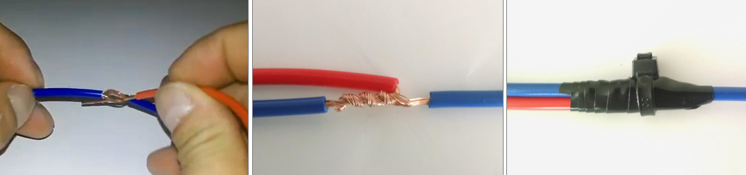
- Snip off the end of the zip tie, and create a stress loop with the attached wire. Apply a zip tie to secure the stress loop with the vehicle’s wire, and then snip off the end of the zip tie.
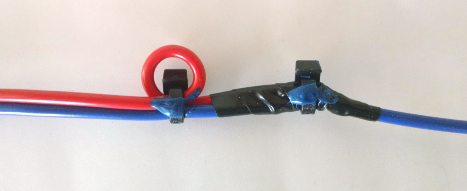
- Repeat this poke-and-wrap / stress-loop technique for connecting the device harness WHITE switched ignition wire to the wire you’ve isolated as the switched power source.
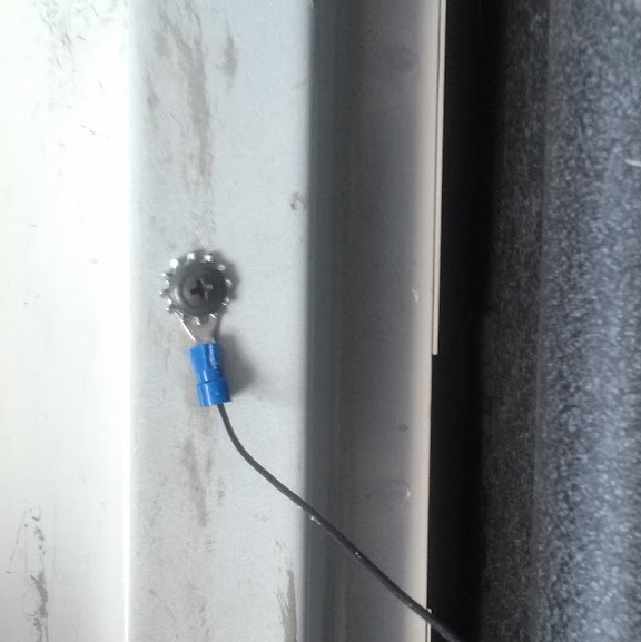
- Crimp a ring terminal to the end of the BLACK ground wire, and secure it to the vehicle’s chassis using a self tapping screw and star washer (internal/external locking washer). Do NOT ground to dash metal.
(Install optional accessories now.)
3. Tape harness wires, and connect the harness to the device.
- Tape off all unused harness wires using electrical tape.
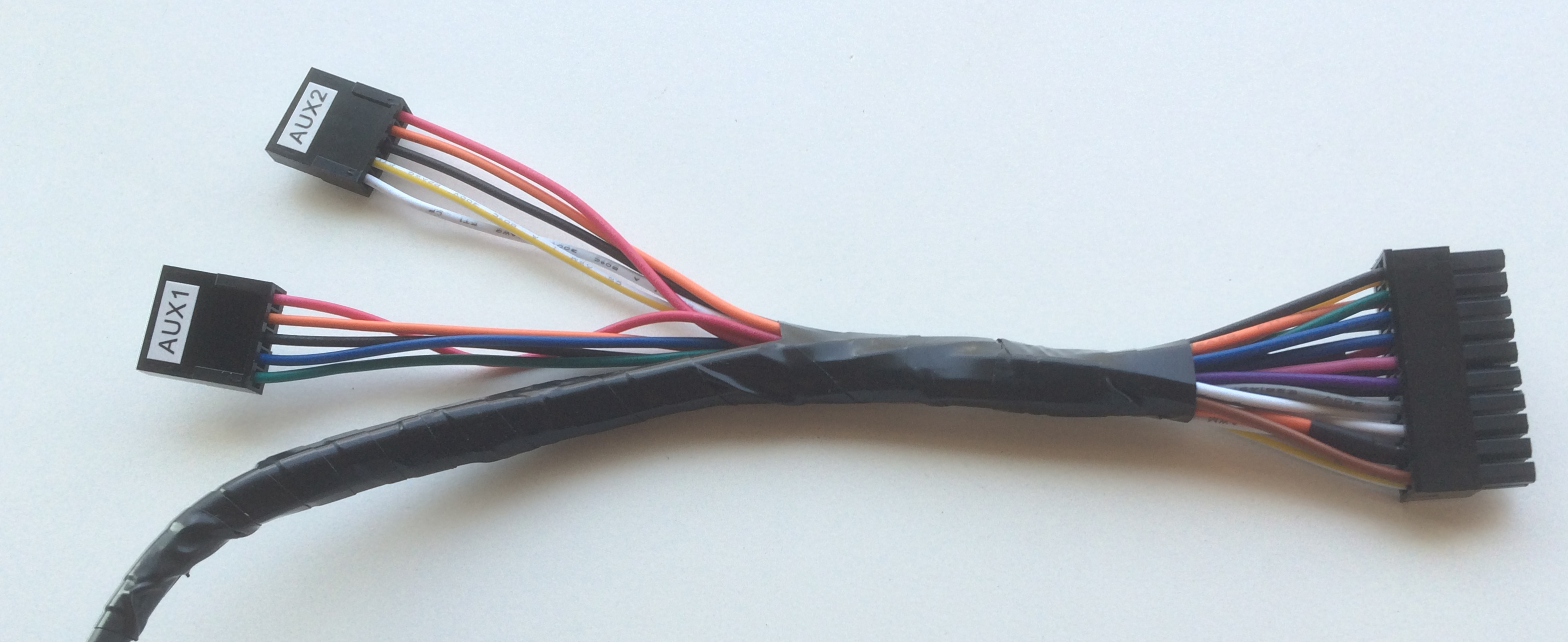
- With the vehicle ignition off, connect the harness to the device.
- Upon successful connection, observe the GPS and Cellular lights on the device. Both lights will begin to blink slowly as the device powers on and will begin to blink faster as it searches for signal. A solid amber light indicates that it has received a cellular lock, and a solid green light indicates it has acquired a GPS lock.
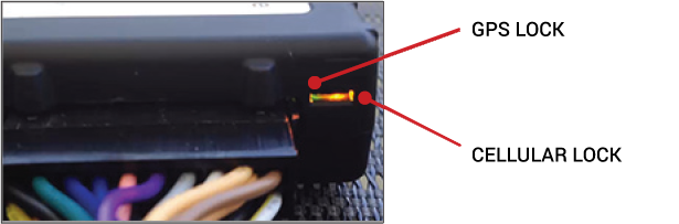
If the installation is taking place in an area with limited view of the sky, the device may not reach full signal until the vehicle has been driven outside of that location.
- Tape off all unused harness wires using electrical tape.
4. Mount the device high within the dash (white sticker facing up).
- Ensure that the white sticker is facing up, and place the device high inside the dashboard as close to the dashboard plastic as possible behind the instrument cluster (but not near the radio).
5.. Verify installation, and tamper-proof remaining connections.
- Do not start the vehicle.
- To activate and register your device, with your vehicle card in hand, call 480-508-7478 or use the GPS Insight Unit Verification App via smart phone (iOS | Android).
- After the installation has been verified, apply tamper seal compound to all connections.