
Before You Begin
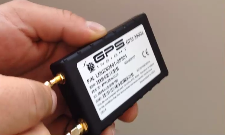
The installation kit contains a registration card, the 3900 device, a 20-pin harness, an external antenna, a heavy-duty 9-pin bypass cable, and a jPOD. Additional tools that you may need include a digital multimeter, zip ties, electrical tape, and tamper seal compound.
Complete the registration card by locating the serial number of the device (labeled “ESN” or “SN”) and copying it onto the card. When the card is complete, you’re ready to start the installation.
Installation Overview
The following steps provide an overview of the installation process:
- Locate the vehicle’s diagnostic port, and ensure proper voltage.
- Install the external antenna, and route the cables.
- Free up existing JPort, and install bypass cable.
- Mount the replacement diagnostic port.
- Prep the harness, and connect the jPOD to the harness AUX 2.
- Connect the antenna cables to the device.
- Connect the harness, and mount the device.
- Connect the jPOD to the bypass cable.
- Verify installation, and tamper-proof remaining connections.
– INSTALL OPTIONAL ACCESSORIES –
Installation Steps
1. Locate the vehicle’s diagnostic port, and ensure proper voltage.
- Remove the lower and upper dashboard panels.
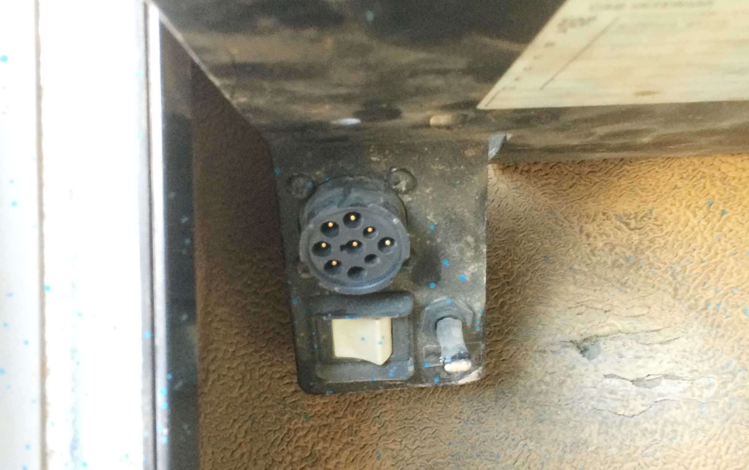
- Locate the vehicle’s 9-pin diagnostic port under the dashboard.
- Turn the vehicle’s master cut-off switch to the ON position (if vehicle is equipped with one).
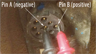
- Use a digital multimeter to test the constant power of the port by placing the positive probe on Pin B and the negative probe on Pin A. The port must provide between 12-24 VDC (+).
2. Install the external antenna, and route the cables.
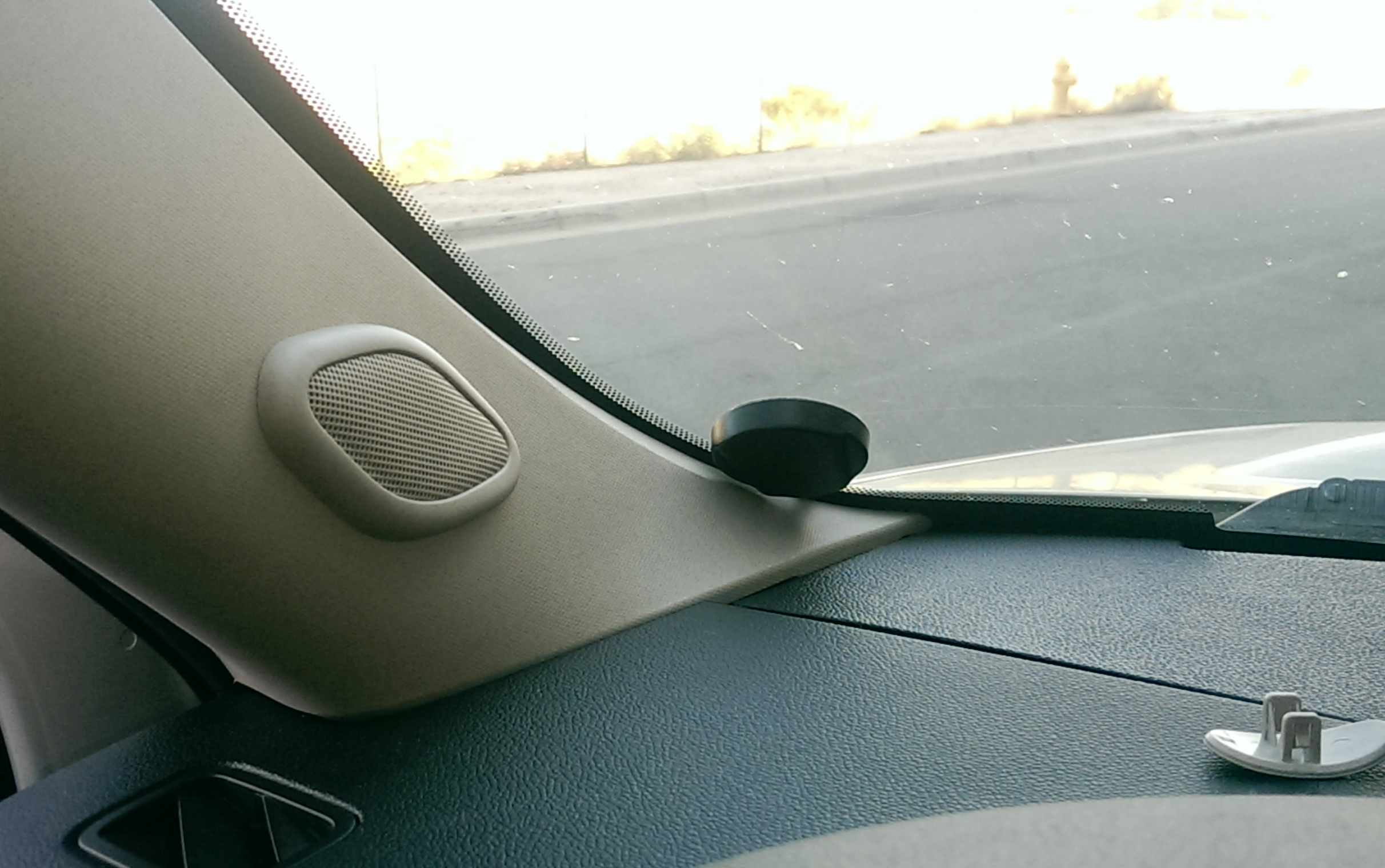
The recommended installation location for the antenna is inside the vehicle on a clear section of the windshield in either of the lower corners as close to the dash as possible.- Remove the A-pillar plastic.
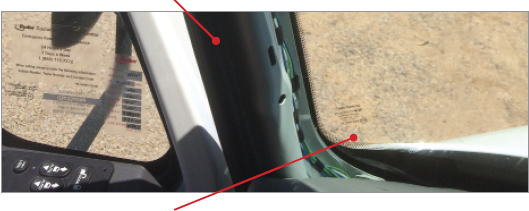
- Prepare the section of the windshield used for mounting by wiping it down with a dry cloth.
- Peel back to expose the antenna’s adhesive, and press the antenna firmly to the windshield to eliminate as many air pockets as possible.
- Route the antenna cables behind the dash cluster where the GPS device will be installed. Stay clear of any moving parts, and ensure the cable will not be pinched or cut when the dash is reassembled.
- Put the A-pillar plastic back into place.
- Remove the A-pillar plastic.
3. Free up existing JPort, and install the bypass cable.
- Free up the existing diagnostic port (JPort) from its current location in the vehicle. This process is typically done by removing the four screws that hold the port into place.
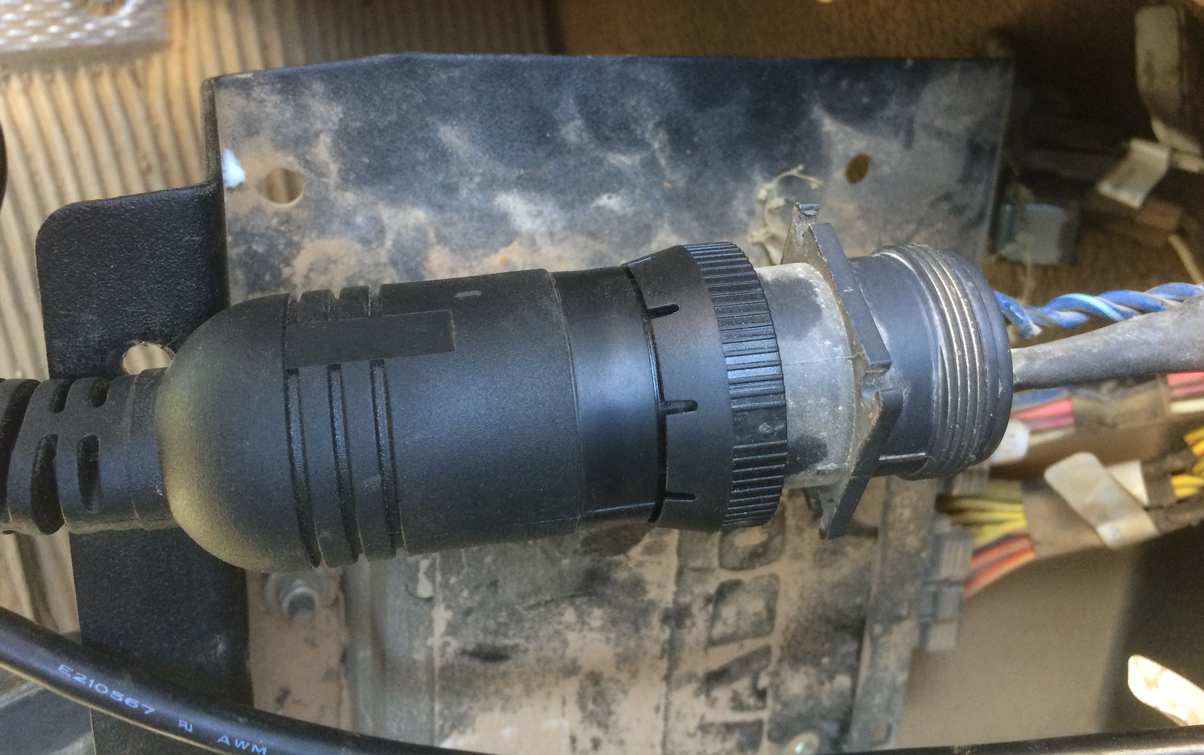
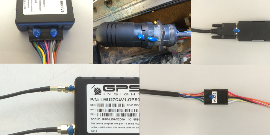
- Plug the bypass connector into the vehicle’s diagnostic port, and turn the threaded coupling to lock the two pieces together.
- Route the bypass cable through the dash so the serial connector is behind the dash cluster.
4. Mount the replacement diagnostic port.
- Mount the replacement diagnostic port using the original screws.
(Install optional accessories.)
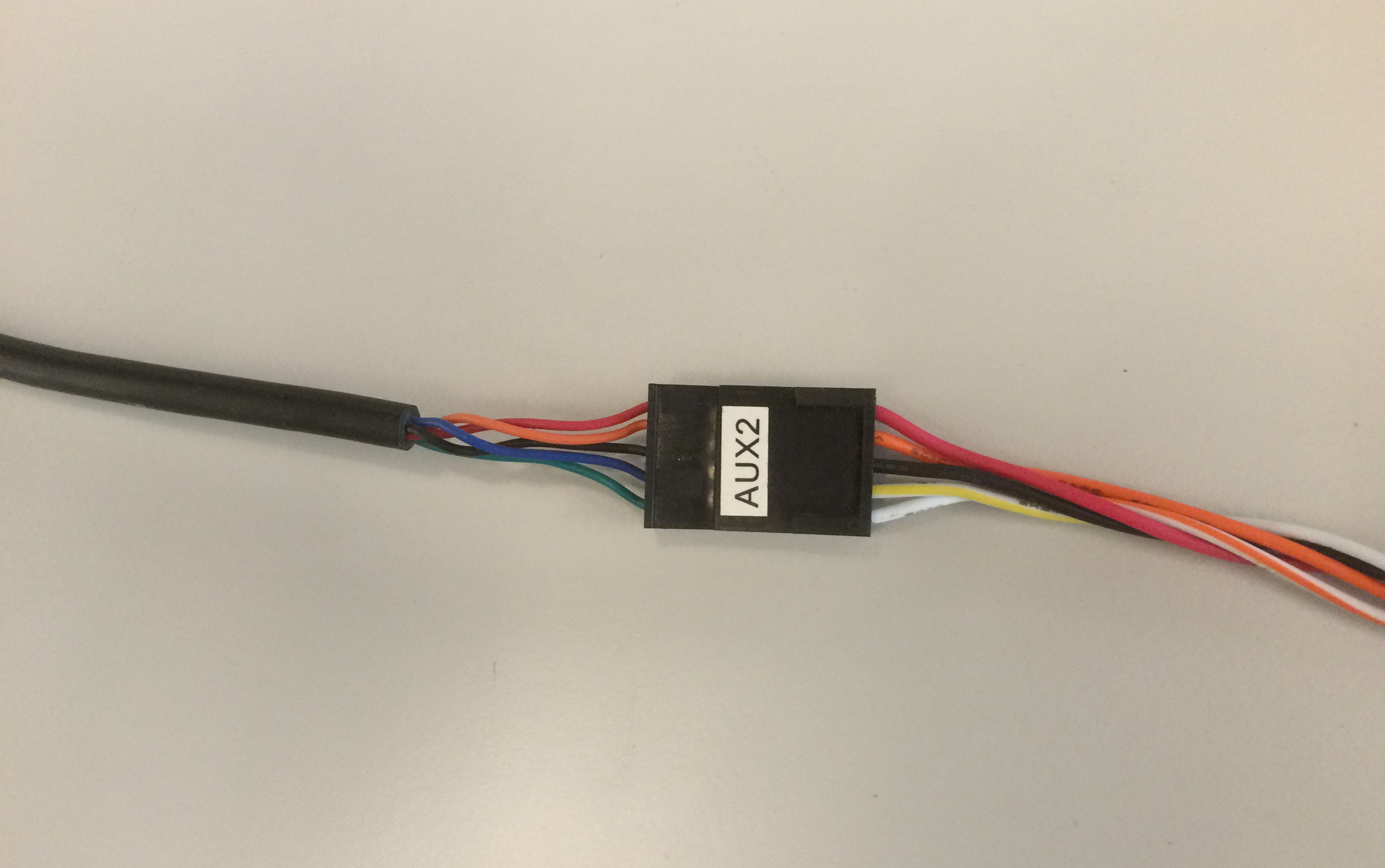
5. Prepare the harness, and connect the JPOD to the harness AUX 2.
- Tape off all unused harness wires. Leave only the AUX ports exposed.
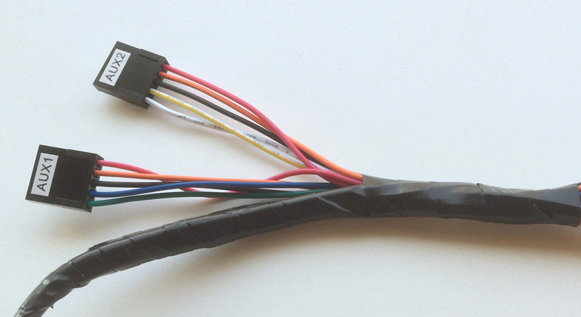
- Connect the jPOD’s 5-pin male connector to the 5-pin female AUX 2 harness connector.
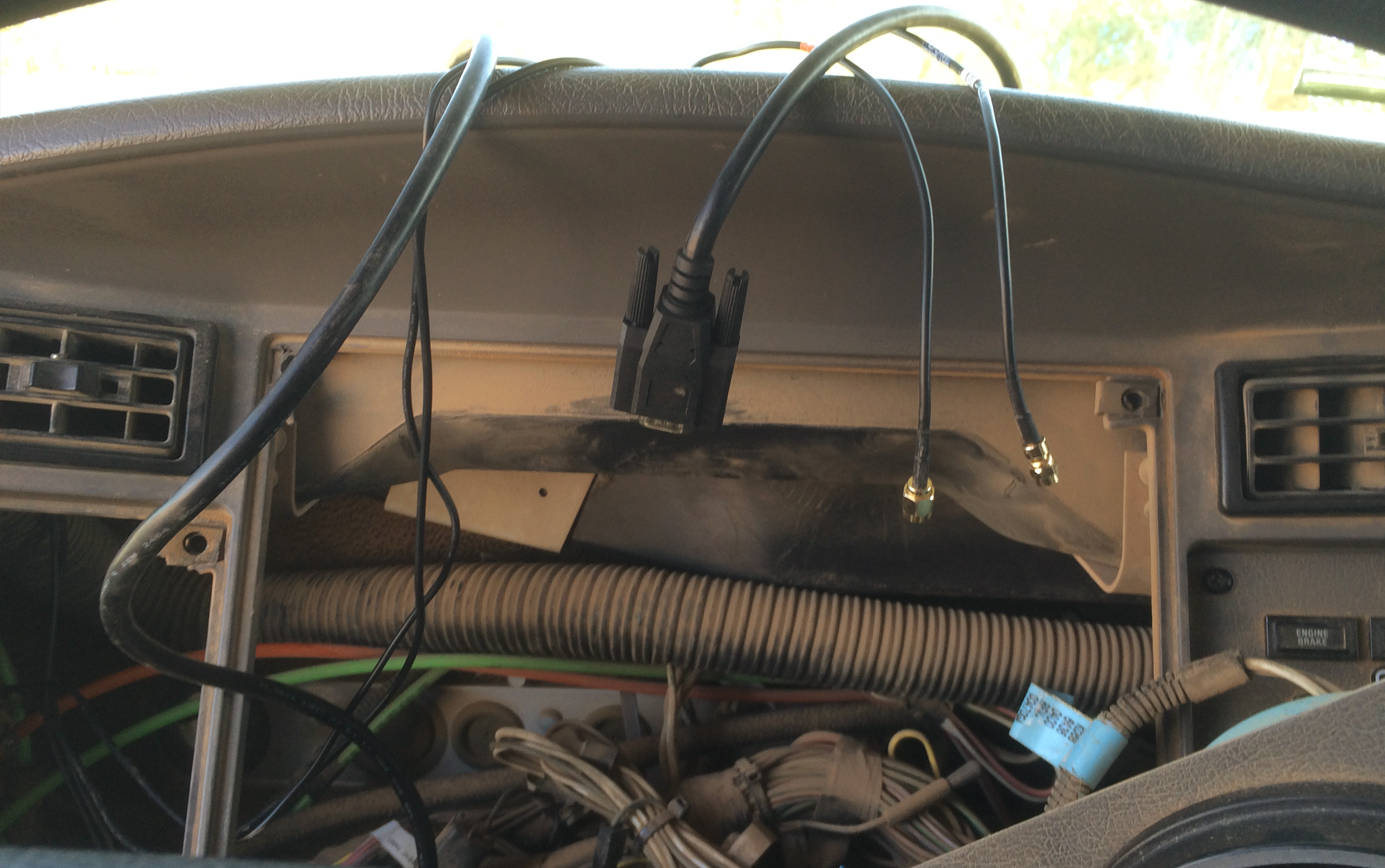
6. Connect the antenna cables to the device.
- Connect both antenna connections to the device. Make sure these connections are finger-tight; do not over-tighten and damage the cable.
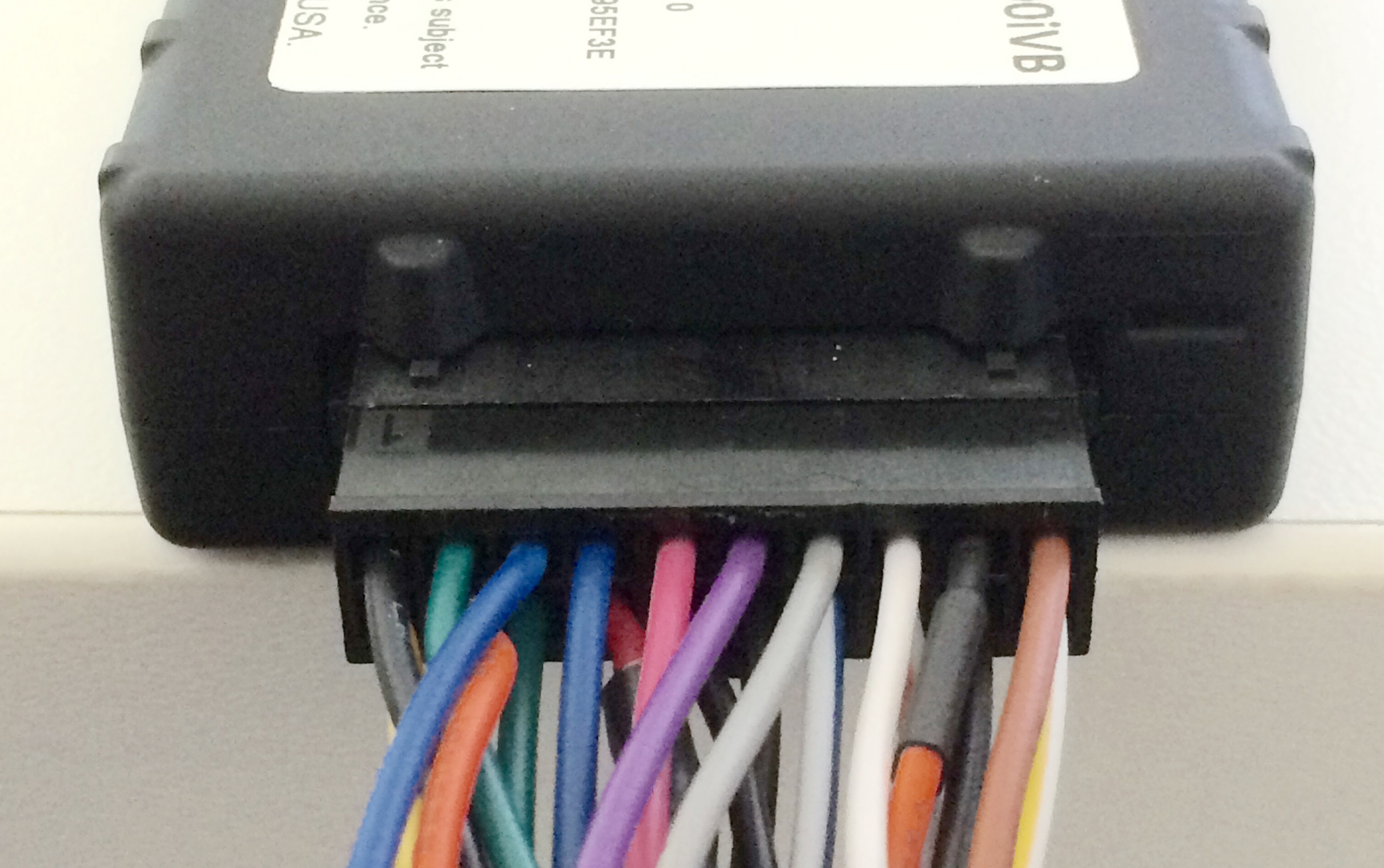
7. Connect the harness, and mount the device.
- Connect the 3900 harness to the GPS device.
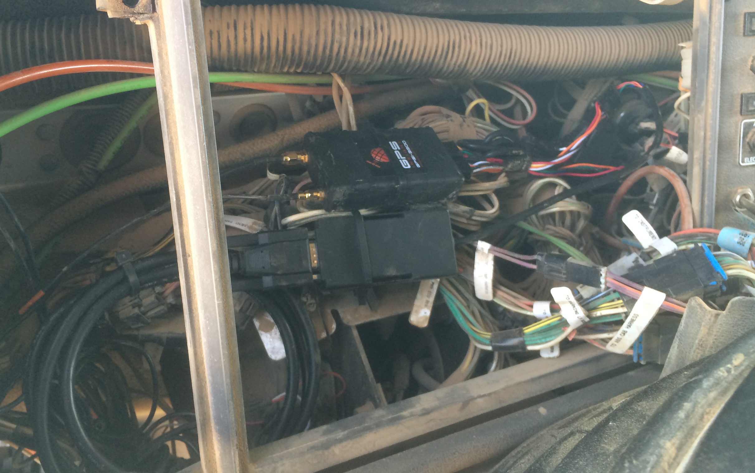
- Place the unit in the area in which you will eventually secure it. Discreet placement of the device is very important. The recommended mounting location is behind the dash cluster.
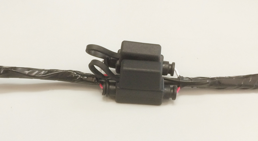
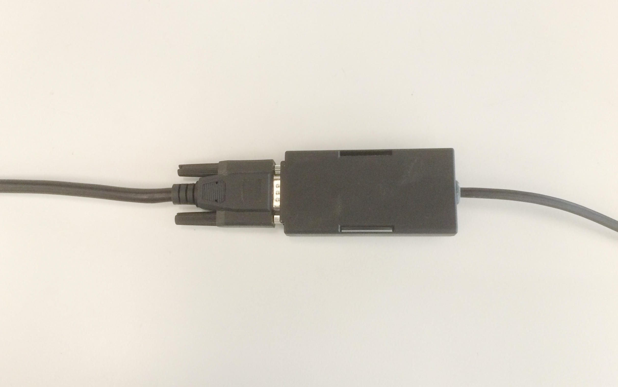
8. Connect the jPOD to the bypass cable.
- With the vehicle ignition off and the keys removed from the igntion, connect the jPOD’s female serial connector to the heavy-duty bypass cable’s male serial connector.
- Screw the two pieces together, finger-tight.
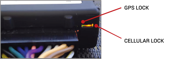
- As the unit powers up, observe the GPS and Cellular lights on the device. Both lights will begin to blink slowly as the device powers on and will begin to blink faster as it searches for signal. A solid amber light indicates that it has received a cellular lock, and a solid green light indicates it has acquired a GPS lock.
9. Verify installation, and tamper-proof remaining connections.
- Do not start the vehicle.
- To activate and register your device, with your vehicle card in hand, call 480-508-7478 or use the GPS Insight Verification App via smart phone (iOS | Android).
- After the installation has been verified, apply tamper seal compound to all connections.
- Coil and zip-tie any excess wires to the vehicle’s existing wiring.
- Reassemble the vehicle’s dashboard, and then give the registration card to your GPS administrator.