The Driver ID kit contains one reader, two key fobs, one plastic washer, one metal-locking washer, one wiretap connector, four butt connectors, four 8 in. (20 cm) cable ties, two 4 in. (10 cm) cable ties, and one buzzer and/or one light.
Additional tools and supplies you need include a cordless drill, one 3/8 in. (10 mm) drill bit, one 1/2 in. (13 mm) drill bit, wire strippers, insulated crimper, and cable ties.
Installation Steps
The following steps provide an overview of the installation process:
- Install preparation.
- Reader and light (if applicable) installation.
- Wire connections.
1. Install preparation.
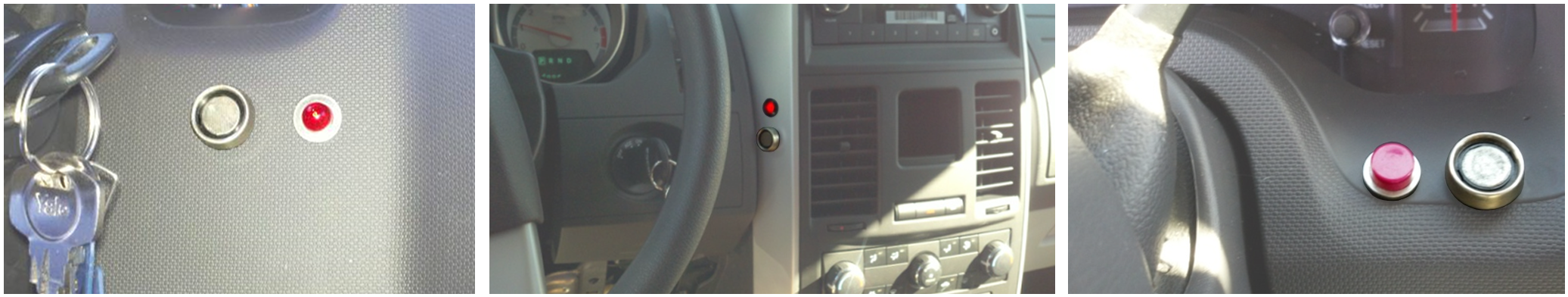
- Before you begin, sit in the driver’s seat to identify a suitable mounting location.
The reader and light (if applicable) should be visible and easy to reach from the driver’s seat.
- Remove the dashboard panel where the reader and light will be installed.
- Confirm that the area directly behind the mounting location is clear and the panel can be put back into place without the reader and light affecting the panel reassembly.
- Before you begin, sit in the driver’s seat to identify a suitable mounting location.
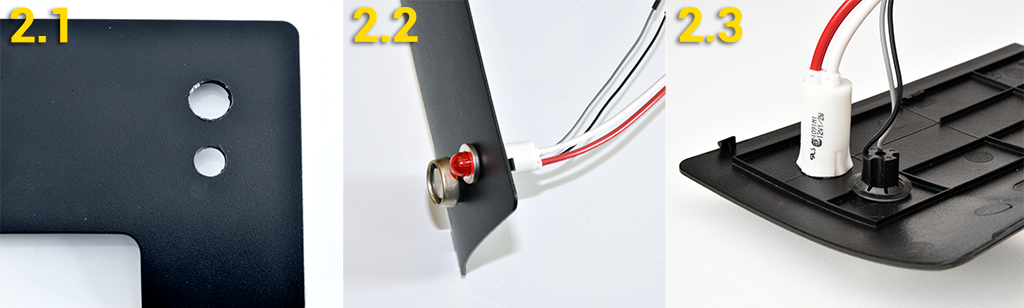
2. Reader and light (if applicable) installation.
Locate the cordless drill, 3/8 in. (10 mm) and 1/2 in. (13 mm) drill bits, reader, light, plastic washer, and metal washer.- Drill a 3/8 in. (10 mm) and 1/2 in. (13 mm) hole approximately 1 in. (3 cm) apart.
- From the front of the dashboard panel, feed both sets of wires through their respective holes and press each flush with the face of the panel.
- Slide the plastic washer, then metal washer, over the reader wires and push tightly against the back side of the dashboard.
Ensure the reader wires are in the plastic grooves before pushing the locking washer tight to the dashboard.
- Route reader and light wires to the GPS device mounting location.
3. Wire connections.
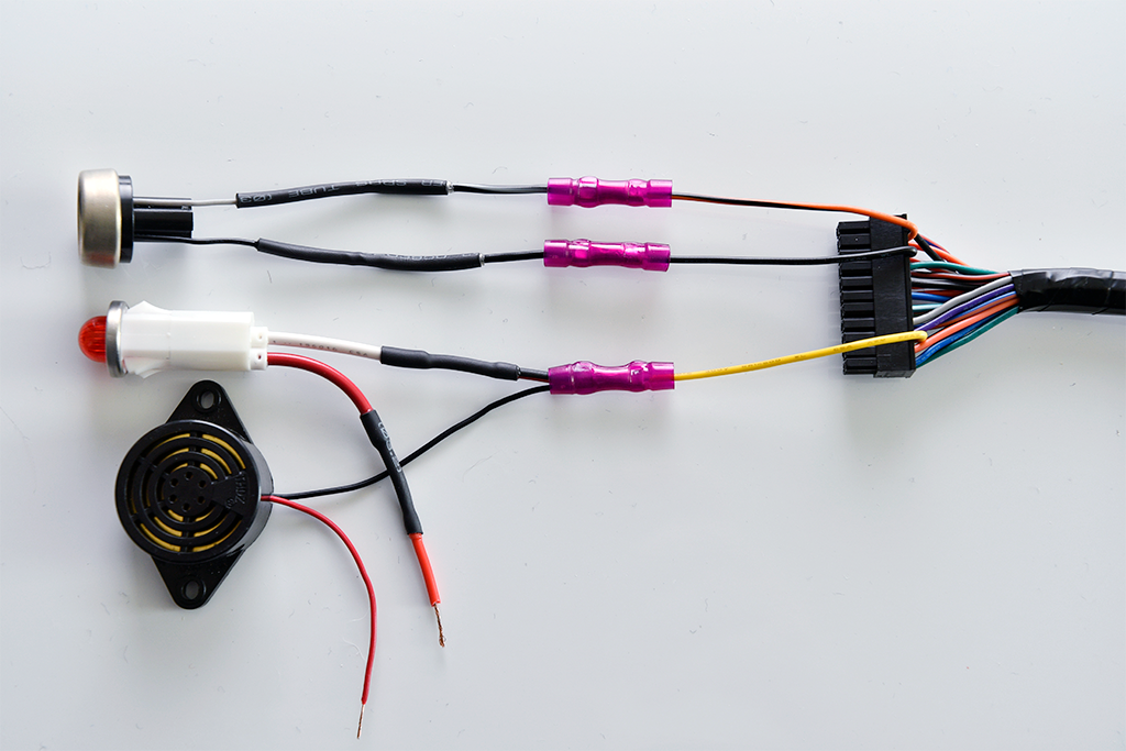
Locate wire strippers, insulated crimper, 22-pin I/O harness, 4-pin power harness, wiretap connector, and three butt connectors.- Remove 1/2 in. (13 mm) of insulation and twist the wire strands of all reader and buzzer/light wires, and the 22-pin I/O harness’ orange with black stripe (pin 10), solid black (pin 11), and yellow (pin 14) wires.
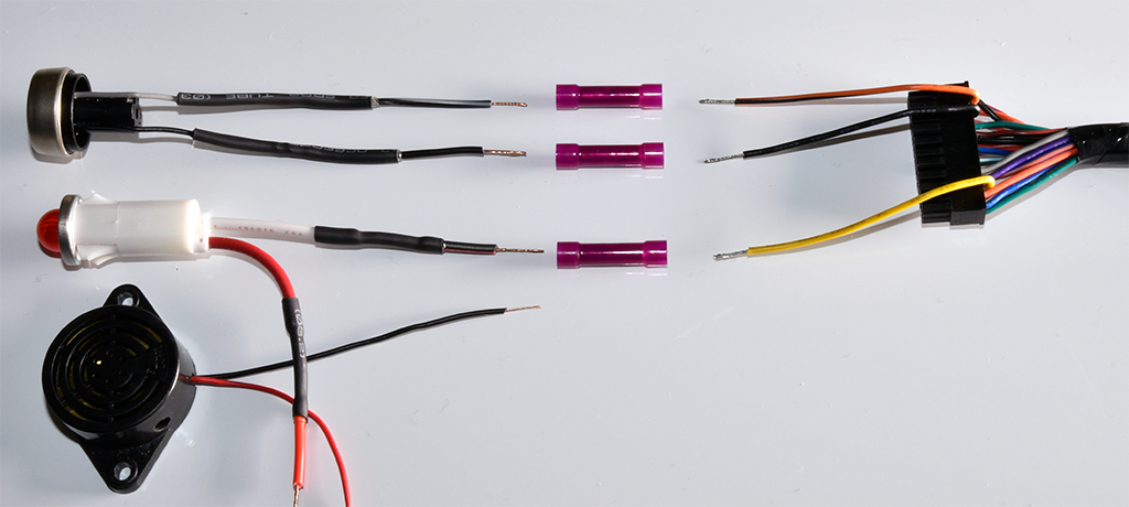
- Crimp together the following:
- Black with gray stripe reader wire to the 22-pin harness’ orange with black stripe wire (pin 10).
- Solid black reader wire to the 22-pin harness’ solid black wire (pin 11).
- Black light/buzzer wire to the 22-pin harness’ yellow wire (pin 14).
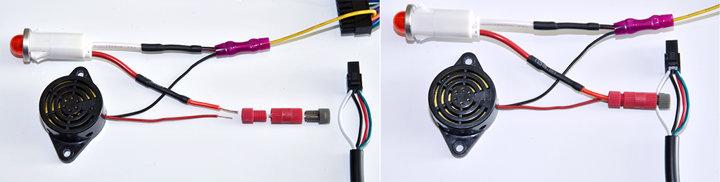
- Unscrew the wiretap connector ends, place the “U”-shaped connector over the 4-pin harness’ white wire (pin 4), then screw on the middle section of the connector. Slide the ring part of the connector over the light’s red wire, then connect it to the middle section and screw finger tight.
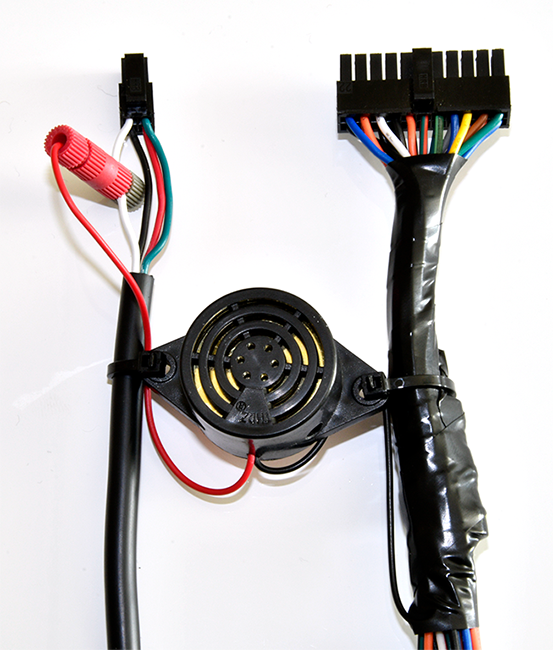
- Secure all loose wires with cable ties. If the buzzer was installed, secure it between the 4-pin power harness and 22-pin I/O harness using the 4 in. (10 cm) cable ties.
- Remove 1/2 in. (13 mm) of insulation and twist the wire strands of all reader and buzzer/light wires, and the 22-pin I/O harness’ orange with black stripe (pin 10), solid black (pin 11), and yellow (pin 14) wires.
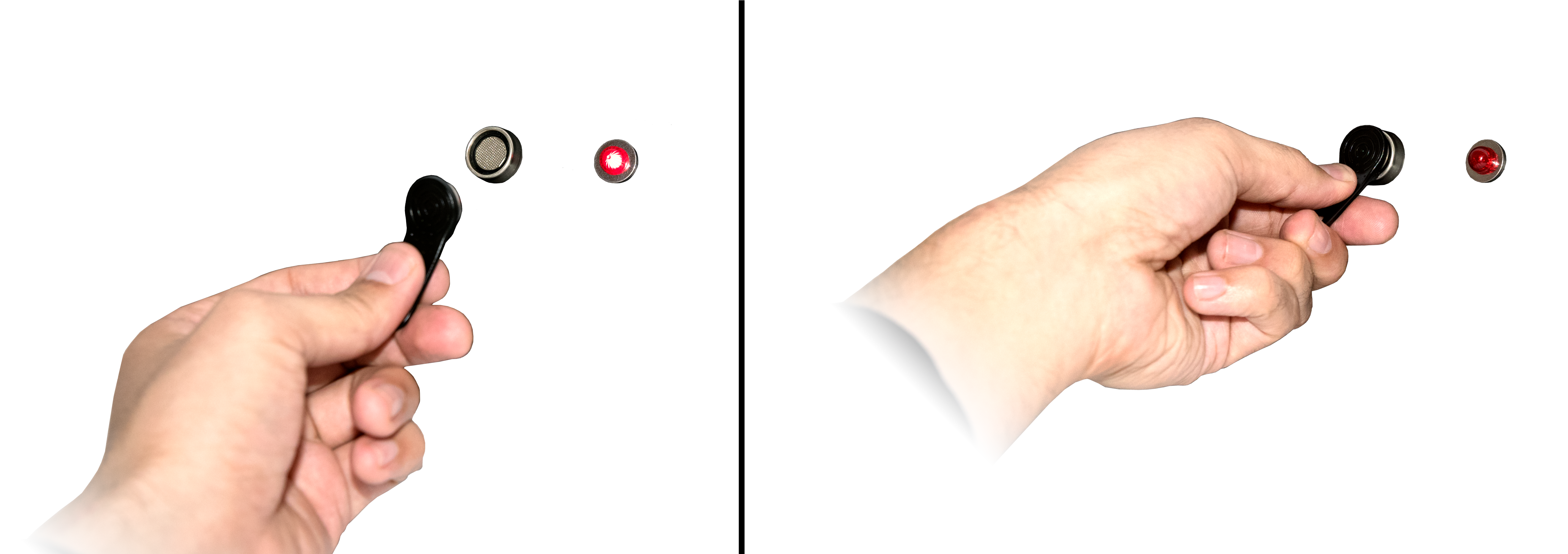
During the installation verification process, you will be required to test this accessory; please make sure you have one of the two key fobs available for the Driver ID testing.
To scan in, press the key fob flat against the reader and slide slightly in any direction so the key fob touches the inner side of the reader. This connection will turn off the light/buzzer.