Before You Begin
The installation kit contains a registration card, installation guide, 4000DM device, antenna, one 34-pin harness, one ring terminal, one self-tapping ground screw, one star washer, eight 8-in. (20 cm) cable ties, six 14-in. (35.5 cm.) cable ties, two fuse holders, two fuses and two butt connectors.
Additional tools and supplies you may need include a cellular phone, razor blade, digital multimeter, 1 1/4 in. (33 mm.) drill bit, insulated crimper, razor knife, wire strippers, crescent wrench, electrical tape, and tamper seal compound.
Installation Steps
The following steps provide an overview of the installation process:
- Install preparation.
- Antenna installation.
- Harness installation.
- Accessory installation (if applicable).
- Cable connections.
- Verify and secure installation.
1. Install preparation.
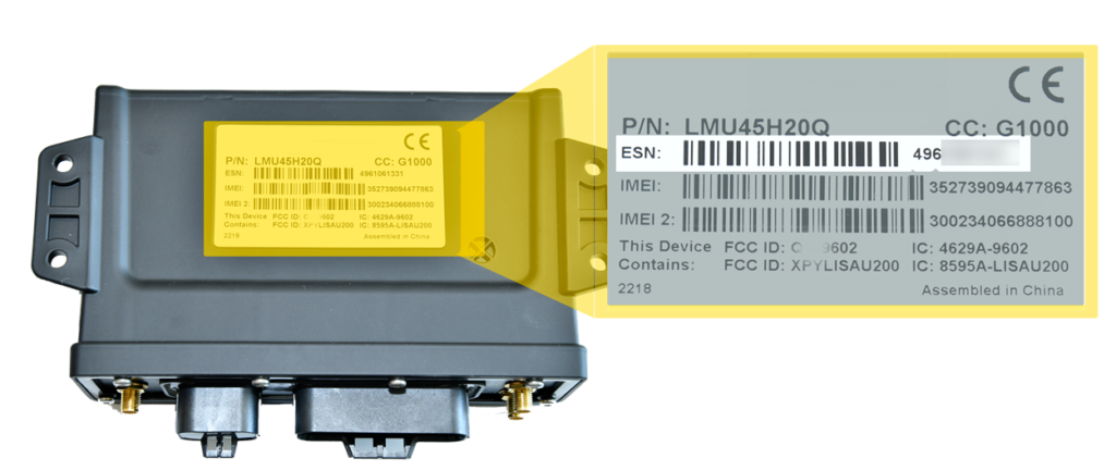
Locate the GPS device, 34-pin harness, two butt connectors, two inline fuse holders, two fuses, wire stripper, insulated crimpers and ring terminal.- Complete the registration card by locating the serial number of the device (labeled “ESN” or “SN”) and copying it onto the card.
4000DM Serial Number location:
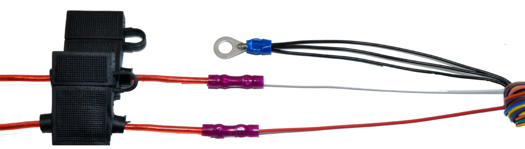
- Insert the fuses into the inline fuse holders.
- Remove 1 in. (2.5 cm.) of insulation from one end of each inline fuse holders and from the red, white and three black wires of the harness. Fray and twist the black wires together and twist the ends of all other wires.
- Crimp a butt connect to each inline fuse holder and to the red and white wires of the harness and the ring terminal to the black wires.
- Remove a-pillar plastic dashboard panels and drop the passenger side head liner for device installation and antenna mounting.
If there is not enough room for the device to be mounted behind the dash cluster, find another location high within the dash that is inaccessible once dash panels are reassembled.
- Complete the registration card by locating the serial number of the device (labeled “ESN” or “SN”) and copying it onto the card.
2. Antenna installation.
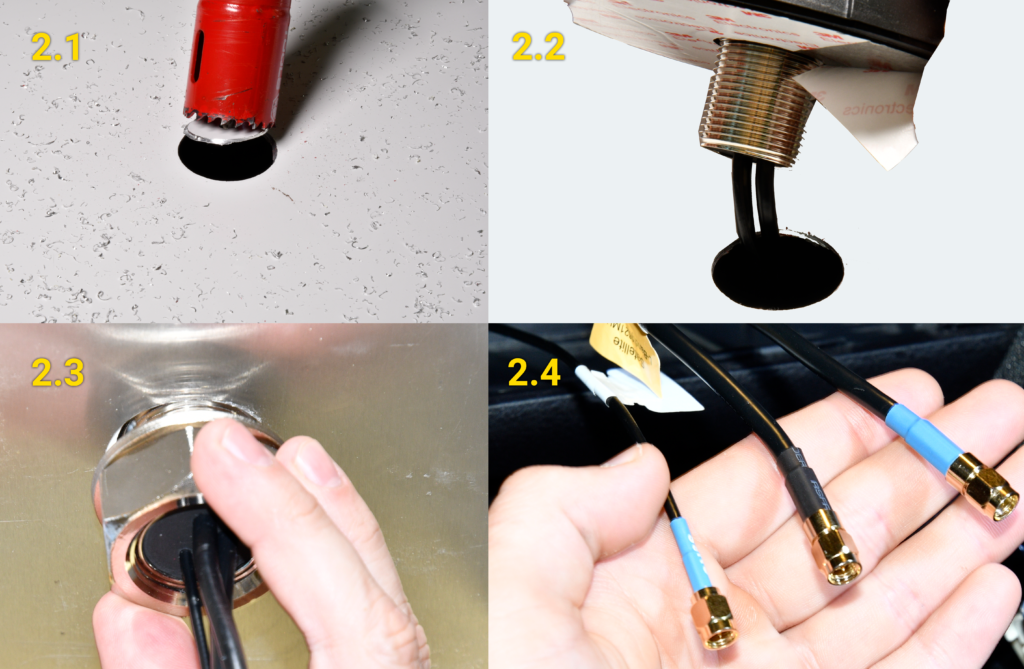
Locate the antenna, cordless drill, crescent wrench and 1 1/4 in. (33 mm.) drill bit and find a flat section where the antenna can be mounted with the best double-sided tape seal.- After confirming nothing will be damaged by the drill bit in the area above the passenger seat, drill the 1 1/4 in. (33 mm.) hole and clear away any metal burs.
- Route the antenna cables through the hole, peel the sticker away exposing the double-sided tape and press the antenna firmly to the roof.
- Slide the washer, then the nut over the wires, screw until snug and tighten with a wrench.
- Route the antenna cables down the a-pillar and to the GPS mounting location behind the dash cluster. Stay clear of any moving parts, and ensure the cables will not be pinched or cut during panel reassembly.
3. Harness installation.
Locate a multimeter, cordless drill, wire stripper, insulated crimper, 34-Pin harness, ground screw, star washer and self-taping screw.Turn the vehicle’s master cut-off switch to the ON position (if the vehicle is equipped with one).
- Identify a vehicle wire which provides at least 12 VDC (+) while the vehicle is on and running and 0 VDC (+) when the key is in the Off and Accessory position. This will be the device’s Ignition Source of power (GPS White Wire).
- Remove the keys from the ignition and using a digital multimeter, locate a vehicle wire which provides between 12 and 24 VDC (+). This will be the device’s Constant Source of power (GPS Red Wire).
- Using a razor knife or wire strippers, remove 1 in. (2.5 cm) of insulation from the vehicle wires identified in Steps 3.1 and 3.2, and poke something nonconductive through the exposed wires to create a loop.
- On the white wire inline fuse, strip off about 1 1/2 in. (4 cm.) of insulation and twist the wire strands before poking it through the loop created for the Ignition source.
- Squeeze the loop shut, and tightly wrap the bare wire around the exposed wire at least three times.
- Fold the wire back and generously wrap electrical tape around the connection, crossing over the insulation on both sides.
- Secure the connection with one zip tie directly over the wire-to-wire connection and another zip tie on a stress loop created about 1 in. (2.5 cm) away from the connection.
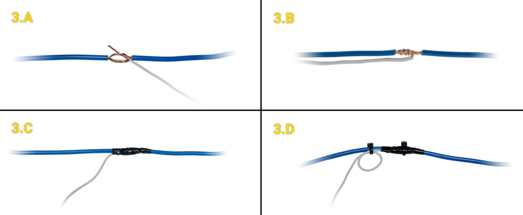
- Repeat the same process for the Red Constant power wire.
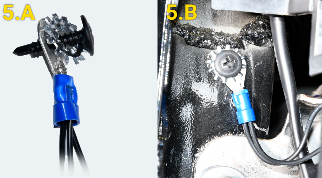
- Locate a suitable location on the chassis to mount the ground wire.
- Slip the star washer over the self-tapping screw first, then over the ring terminal.
- Screw the wire to the chassis after confirming there is nothing behind the mounting location.
4. Accessory installation.
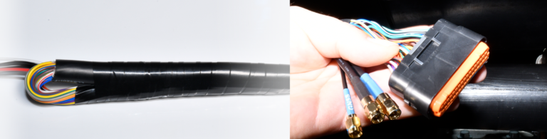
If your installation has any accessories, please refer to the corresponding guide now.- After installing accessories or if you do not have any accessories, tape all unused wires to the harness using electrical tape and route the cable to the device mounting location.
5. Cable connections.
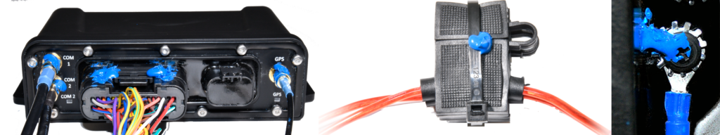
Locate the GPS device.- Connect all three antenna connections to the GPS device (use the reference table below) ensuring the connections are finger-tight; do not over-tighten and damage the cables.
- Connect the 34-pin harness to the GPS device.
- As the GPS device powers up, observe the LEDs. All three will blink slowly and will begin to blink faster as it searches for signal. Solid LEDs indicate the required connection have been made.
If the installation is taking place in an area with limited view of the sky or is in area without cellular coverage, the device may not reach full signal until the vehicle has been moved outside of that location.
Antenna Device Cellular COM 1 Satellite COM 2 GNSS GPS 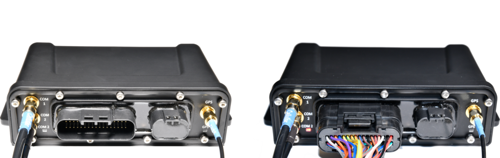
6. Verify and secure installation.
Locate a cell phone, registration card, cable ties, wire cutter and tamper seal.- To activate and register your device, with your vehicle card in hand, call 480-508-7478 or use the GPS Insight Verification App via smart phone (iOS | Android).
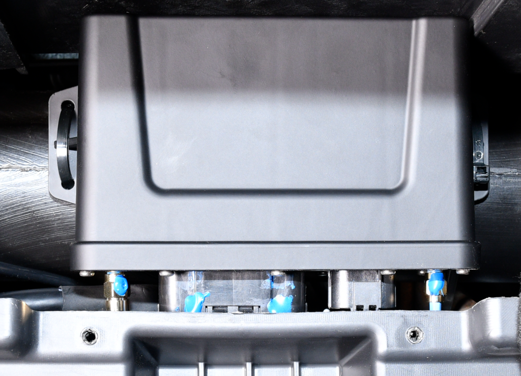
- Upon successful install verification and registration; cable tie any/loose cables, apply tamper seal to all connections (if available), secure the device behind the dash cluster, reassemble the vehicles dash and give the registration card to your GPS administrator.