
The installation kit contains the temperature sensor, one p-clamp, two heat-shrink butt connectors, two standard butt connectors, two grommets, eight 8-in. (20 cm) cable ties with screw holes, twelve 8-in. (20 cm) cable ties, nine self-tapping screws, and one 18-ft. cable extension.
Additional tools and parts you may need include electrical tape, insulated wire crimper, wire stripper, 20 Ga wire or larger, extension ladder, cordless drill, extended length 5/16 (8 mm) drill bit, heat gun, heat-shrink butt connectors, cable ties, and split loom.
Installation Steps
The following steps provide an overview of the installation process:
- Install preparation.
- Mounting.
- Wire connections.
1. Install Preparation.
- Inside of the trailer, locate an area on the left that is ~1 ft. (30 cm) down from the ceiling and ~1 ft. (30 cm) from the wall. Verify nothing in this area will be damaged when drilling the hole for the temperature sensor.
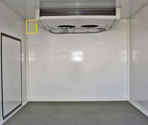
- Identify a cable route from the temperature sensor location to the GPSI-4000. The cable placement should not prevent the use or removal of asset panels and should not leave the cable open to damage.
- Determine whether the route requires the temperature sensor cable to be extended.
If the cable must be extended, you must use heat-shrink butt connectors and all wires must be protected with split loom.
- Inside of the trailer, locate an area on the left that is ~1 ft. (30 cm) down from the ceiling and ~1 ft. (30 cm) from the wall. Verify nothing in this area will be damaged when drilling the hole for the temperature sensor.
2. Mounting.
- Locate the cordless drill, extended length 5/16 (8 mm) drill bit, temperature sensor, two grommets, one self-tapping screw, and the p-clamp.
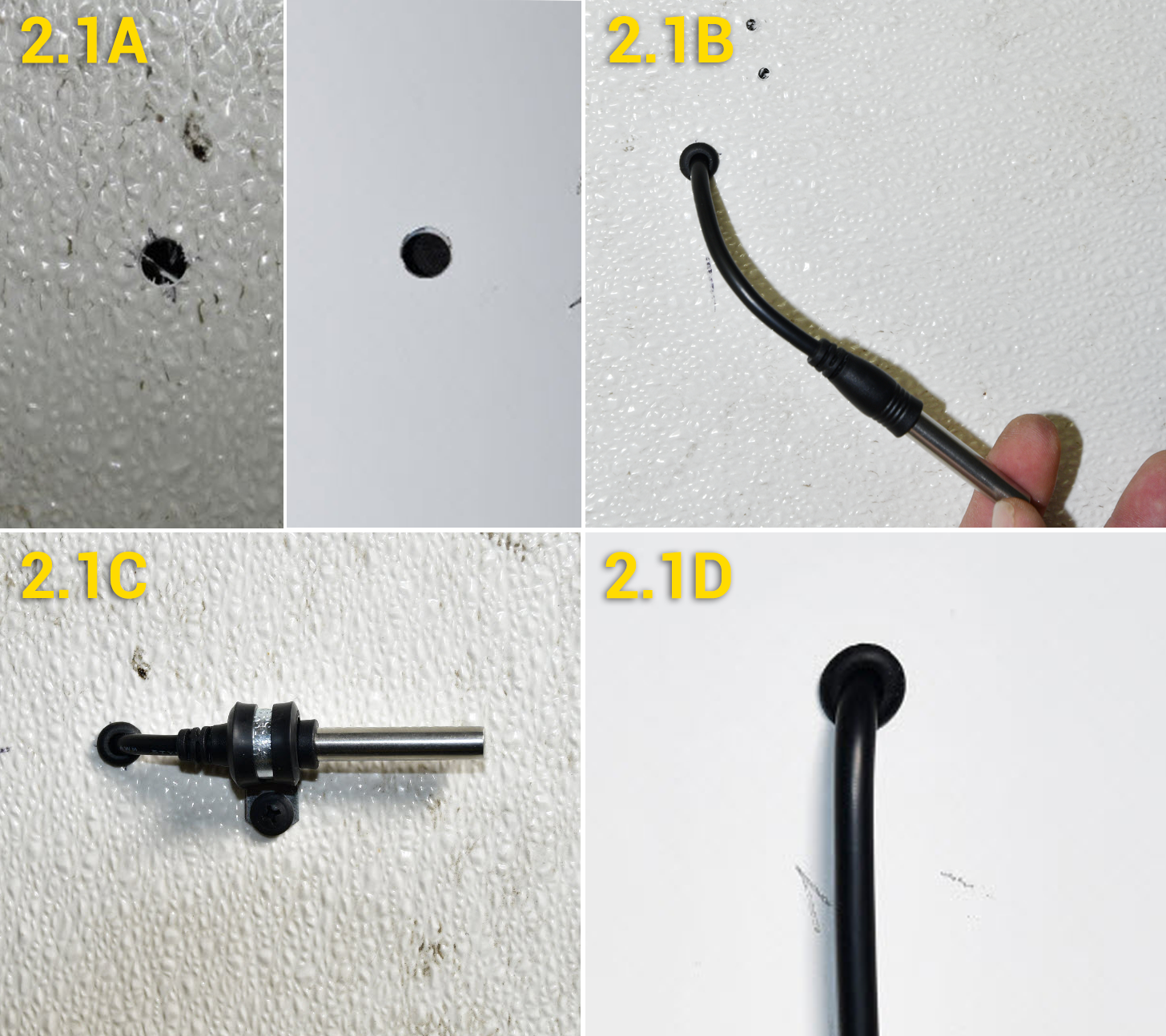
- Drill a hole in the area identified in Step 1 – Install Preparation, and clear away any metal burs that could damage the cable.
- Slide a grommet over the temperature sensor cable, and from the inside of the trailer, feed the temperature sensor cable through the hole, and slide the grommet in place.
- Place the p-clamp over the plastic portion of the sensor, and hold the sensor horizontal to the ground as you screw the p-clamp in place.
- Slide the second grommet over the cable and into place.
- Using cable ties, secure the temperature sensor cable every 1 1/2 ft. as you route the cable from outside to inside the cab, and behind the dashboard cluster.
- Locate the cordless drill, extended length 5/16 (8 mm) drill bit, temperature sensor, two grommets, one self-tapping screw, and the p-clamp.
3. Wire Connections.
- Locate the wire strippers, insulated crimper, two heat-shrink butt connectors, two standard butt connectors, cable extension wire, the GPSI-4000 22-Pin I/O Harness, and a heat gun.
- Temperature Sensor
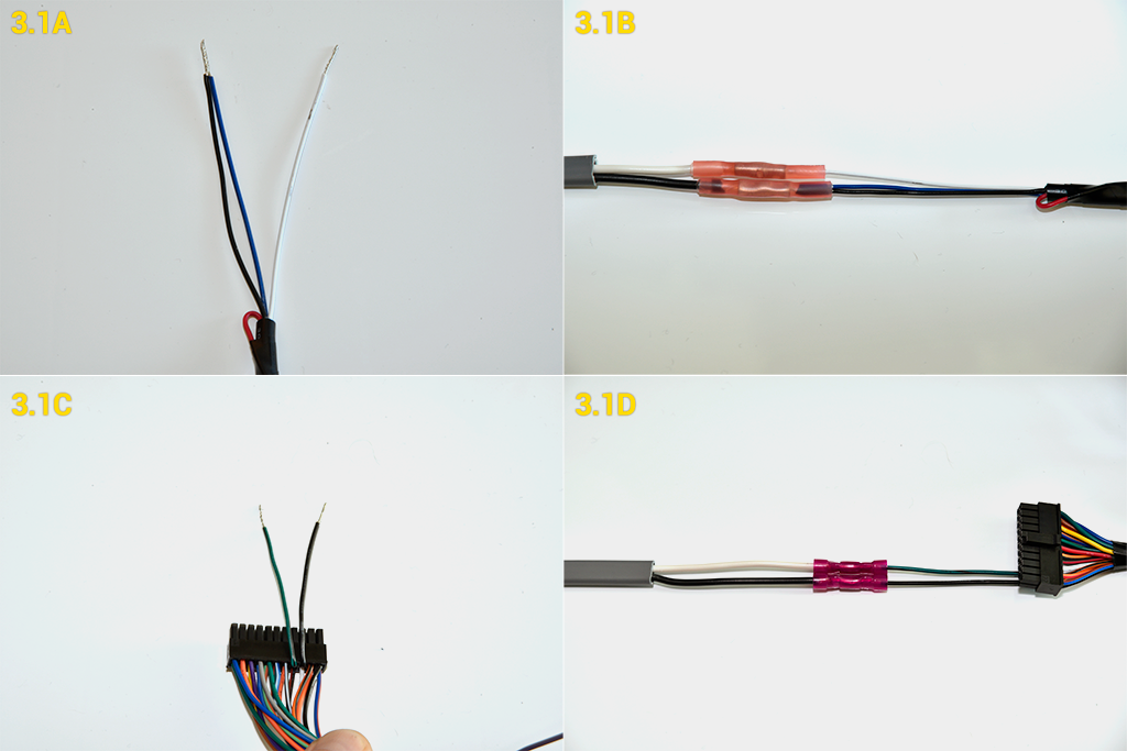
- Tape off the red wire. Remove 1/2 in. (12 mm) of insulation from the blue, black and white wires. Twist the wire strands for the white wire. Fray the wire strands of the blue and black wires before twisting them together.
- Remove 1/2 in. (12 mm) of insulation from both cable extension wires. Twist the ends of all wires. Using heat-shrink butt connectors, connect the temperature sensor black and blue wires to the extension cable black wire, then the white wire to white wire. Apply heat to the butt connectors after crimping.
- GPSI-4000 22-Pin I/O Harness
- Locate the green with black stripe (pin 8) and solid black (pin 9) wires. Remove 1/2 in. (12 mm) of insulation and twist the strands of each wire.
- Using standard butt connectors, connect the 22-pin I/O harness black wire (pin 9) to the temperature sensor extension black wire, and the 22-pin I/O harness green with black stripe wire (pin 8) to the temperature sensor extension white wire.
Heat must be applied to every heat-shrink butt connector to ensure there’s a water-tight seal. When applying heat, glue will seep from the butt connector; do not overheat the connection as this can cause damage to the wire or surrounding wires.
- Temperature Sensor
- Locate the electrical tape and tape off all unused wires.
- Locate the wire strippers, insulated crimper, two heat-shrink butt connectors, two standard butt connectors, cable extension wire, the GPSI-4000 22-Pin I/O Harness, and a heat gun.