Before You Begin
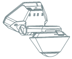
The installation kit contains a registration card, the Drive360 device, device dock, mount plate with adhesive, hardwire power harness and hardwire accessories (2 fuse holders, 2 heat-shrink butt connectors, 1 ring terminal, 1 star washer and 1 ground screw).
If you are not familiar with testing and installing power system related items, professional installation assistance by a qualified installation vendor or dealer is recommended.
Installation Overview
The following steps provide an overview of the installation process:
- Device Connections.
- Device Mounting.
- Adjust Angle.
- Verify Installation.
Installation Steps
1. Device Connections.
- With keys removed from the ignition, locate a vehicle wire providing 12 to 14 VDC (+). This will be the constant power wire power source.
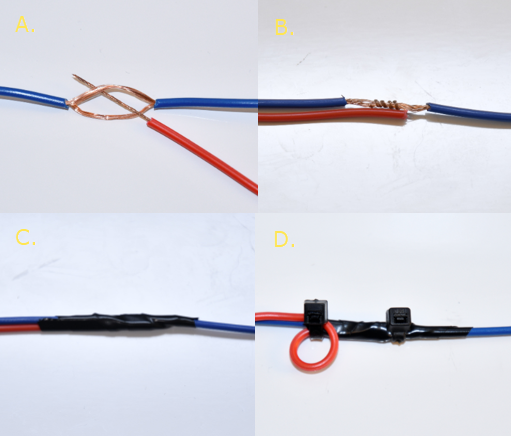
- Complete the following steps to poke and wrap the connection:
Manufacturer-supplied hardwire accessories which include fuse taps MAY BE included in your order. Do NOT use these fuse taps. Instead, follow the poke-and-wrap guidelines below.
- Prep the power harness by cutting the existing connections and adding supplied in-line fuse holders to constant (red) and ignition (white) wires and add ring terminal to ground (black) wire.
- Remove 1 in. (2.5 cm) of insulation from the vehicle wire identified, poke something non-conductive between the wire strands creating a loop and insert the harness Red wire.
- Squeeze the loop shut, tightly wrap the bare wire around the exposed wire at least three times and fold the wire over the connection.
- Generously wrap electrical tape around the connection, crossing over the insulation on both sides.
- Secure the connection with one cable tie directly over the wire-to-wire connection and another creating a stress loop created about 1 in. (2.5 cm) away from the connection.
- Locate a vehicle wire which provides at least 12 VDC (+) and 14 VDC (+) while the vehicle is On and running and 0 VDC (+) when the key is in the Off and Accessory position; this will be the 6-Pin Harness White wire power source.
- Repeat Step 2.2: A-E to make the same type of wire-to-wire connection for the Switch/White wire.
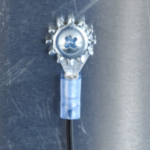
- Locate a suitable location on the chassis to attach the device Black/Ground wire. Confirm there is nothing behind the mounting location and screw the ring terminal to the chassis.
- Route the wire with USB Type-C plug of the Power Cord to the expected camera mounting location on the windshield.
- Secure any excess wire after the camera is mounted.
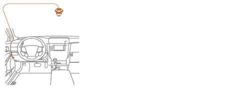
Leave an extra few inches of cord length near the camera to insert the Type-C plug into the Drive360 4G Dock, and also make mounting and dismounting the camera easier.
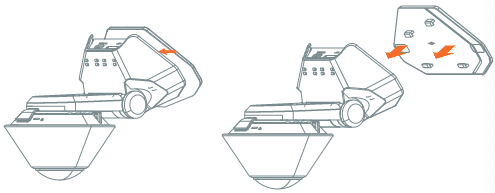
2. Device Mounting.
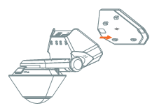
- With the Mount Plate attached to the windshield and the power cord connected to the Drive360 4G, position the Drive360 4G on the right side of the Mount Plate. Next, ensure the Mount Plate locking tabs are aligned with their fittings on the camera dock.
- Slide the camera left to secure it firmly onto the Mount Plate.
Please ensure the Drive360 4G is installed properly and firmly attached to the windshield prior to operating the vehicle. Be sure to make any adjustments to the angle or position of the Drive360 4G prior to operating the vehicle.
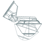
3. Adjust Angle.
- Use a coin to loosen the Dock hinge by turning the adjustment slot counter-clockwise.
- For optimal vision in and around your vehicle, adjust the camera’s position to make the Dock hinge parallel with the road.
- Tighten the Dock into place by turning the adjustment slot clockwise with a coin.
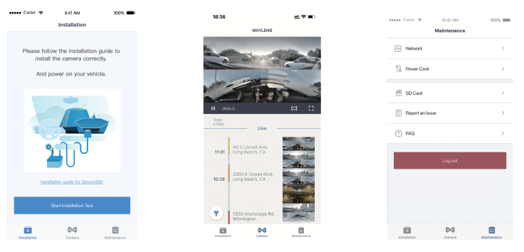
4. Verify Installation.
After installing the Drive360, you should use the Waylens Fleet App to verify your installation. You should verify installation by checking the following points:- Check the power cord connection.
- Check the Network.
- Confirm video streams.
- Connect the camera using mobile phone via WiFi.
- Tap Start Installation Test.
- Check the video streams from the Camera page.
The app will enter the process of Installation Test, including Power Cord Test and Network Test. Alternatively, you can do the Power Cord Test and Network Test separately from the “Maintenance” page.
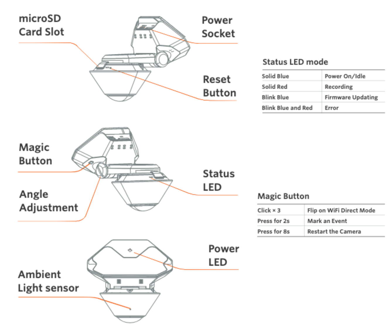
LED Mode/Button Overview
De-Installation
1. Removing the Drive360 Device.
- Slide the Drive360 4G Dock to the right and carefully pull the camera away from the Mount Plate once you feel it release from the locking tabs.
- Remove the power connection from the rear of the camera.